Manuals
/
Bunn
/
Kitchen Appliance
/
Coffeemaker
Bunn
twf-ez
service manual
Service, Component Access
Models:
twf-ez
1
15
26
26
Download
26 pages
30.25 Kb
12
13
14
15
16
17
18
19
Troubleshooting
C.Ready Indicator
Problem
Diagnostics
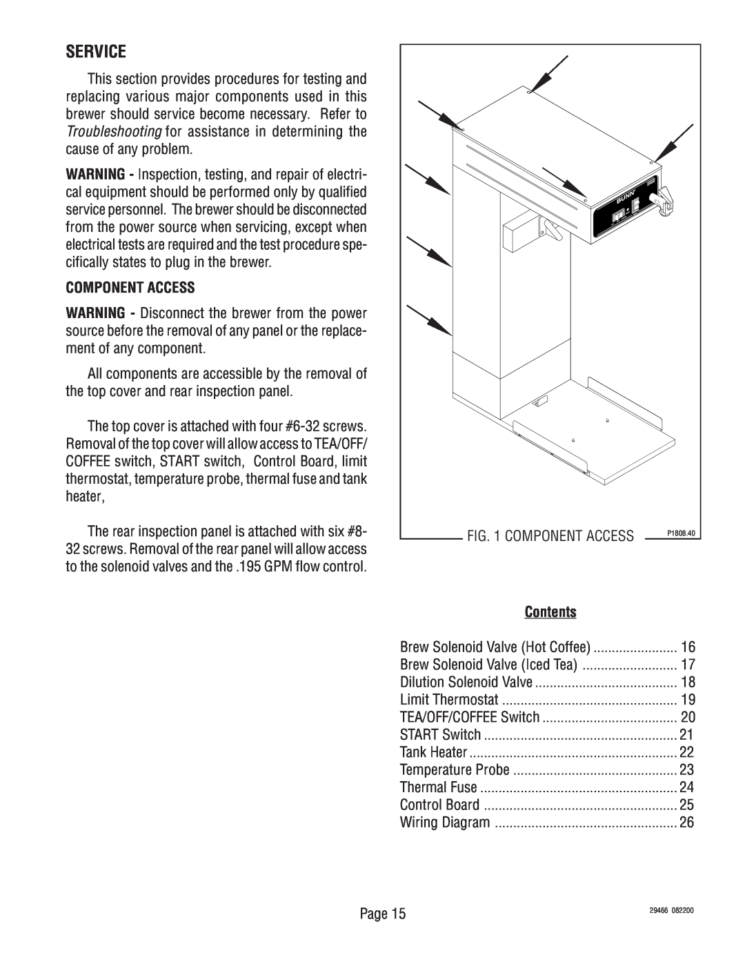
Component Access
Settings. See page
Adjusting Brew Volumes
SERVICE cont
Page 15
Image 15
Page 14
Page 16
Page 15
Image 15
Page 14
Page 16
Contents
DISCONTINUED VERSION
POST OFFICE BOX SPRINGFIELD, ILLINOIS
TELEPHONE 217 529-6601FAX
BUNN TWF-EZ
CONTENTS
WARRANTY
INTRODUCTION
USER NOTICES
#00831.0000 #00656.0000 #03408.0000 #03409.0000
061599
ELECTRICAL REQUIREMENTS
PLUMBING REQUIREMENTS
Electrical Hook-Up
INITIAL SET-UP
C.Ready Indicator
CLEANING
A.TEA/OFF/COFFEE Switch
B.Start Switch
Adjusting Brew Volumes
TWF-EZADJUSTMENTS & OPTIONAL SETTINGS
TROUBLESHOOTING
REMEDY
TROUBLESHOOTING cont BREW CIRCUIT
PROBLEM
PROBABLE CAUSE
TROUBLESHOOTING cont BREW CIRCUIT PROBLEM
Settings. See page
2. Funnel loading
main in the funnel
TROUBLESHOOTING cont HEATING CIRCUIT PROBLEM
FLASHES
DIAGNOSTICS
CAUSE
THINGS TO CHECK
COMPONENT ACCESS
SERVICE
BREW SOLENOID VALVE HOT COFFEE
SERVICE cont
BREW SOLENOID VALVE ICED TEA
DILUTION SOLENOID VALVE
SERVICE cont LIMIT THERMOSTAT
SERVICE cont TEA/OFF/COFFEE SWITCH
SERVICE cont START SWITCH
SERVICE cont TANK HEATER
SERVICE cont TEMPERATURE PROBE
SERVICE cont THERMAL FUSE
SERVICE cont CONTROL BOARD
Page
29466
082200
Top
Page
Image
Contents