II. Preparation for Installation
The Walk’n Roller requires the assembly and attachment of 3 components: handlebar, parking brake, and stroller wheel. These are covered in sections III, V, and VII. Each section has its associated part list so that you may confirm that you have received all the parts needed. If any parts are missing contact Burley, do not proceed with installation.
Tools Required:
7/16 inch wrench | No. 2 Phillips screwdriver |
Torque wrench | No. 3 Phillips screwdriver |
Extension | Some adhesive tape |
7/16 inch socket |
|
Note: The No 2 Phillips screwdriver has a shaft diameter of ¼ inch or less and is most useful here for making bolts holes through fabric. The No. 3 driver has a larger shaft (almost 1/3 inch) and is the better fit for tightening the bolts of this assembly.
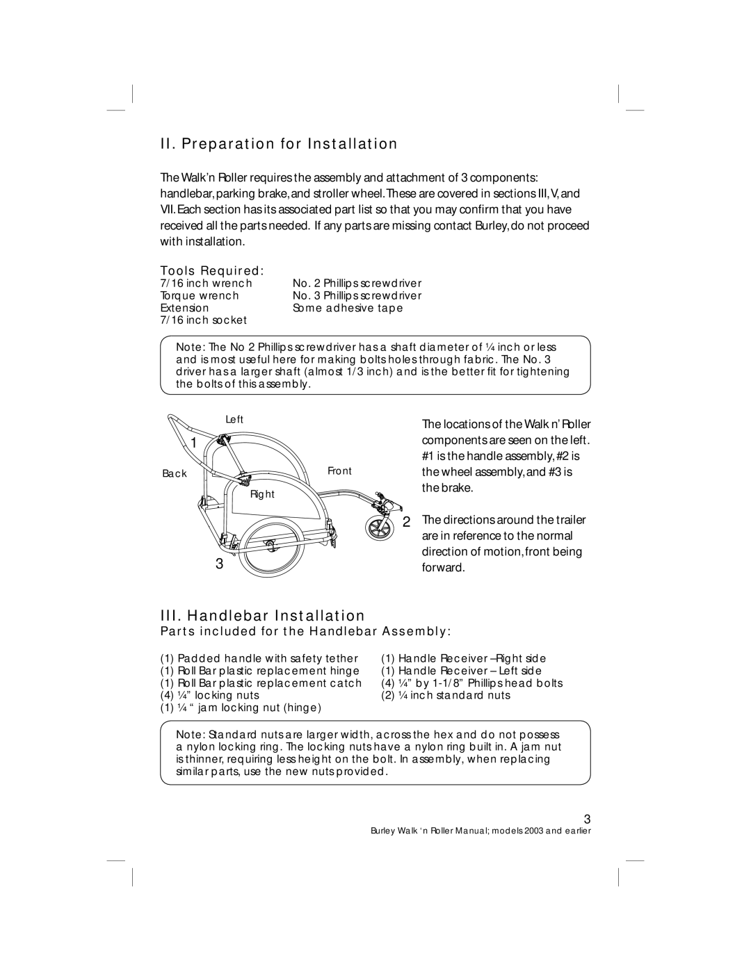
| Left | The locations of the Walk n’ Roller |
|
| |
| 1 | components are seen on the left. |
|
| #1 is the handle assembly, #2 is |
Back | Front | the wheel assembly, and #3 is |
| Right | the brake. |
|
| |
| 2 | The directions around the trailer |
|
| are in reference to the normal |
| 3 | direction of motion, front being |
| forward. |
III. Handlebar Installation
Parts included for the Handlebar Assembly:
(1) | Padded handle with safety tether | (1) | Handle Receiver |
(1) | Roll Bar plastic replacement hinge | (1) | Handle Receiver – Left side |
(1) | Roll Bar plastic replacement catch | (4) | ¼” by |
(4) | ¼” locking nuts | (2) | ¼ inch standard nuts |
(1) | ¼ “ jam locking nut (hinge) |
|
|
Note: Standard nuts are larger width, across the hex and do not possess a nylon locking ring. The locking nuts have a nylon ring built in. A jam nut is thinner, requiring less height on the bolt. In assembly, when replacing similar parts, use the new nuts provided.
3
Burley Walk ‘n Roller Manual; models 2003 and earlier