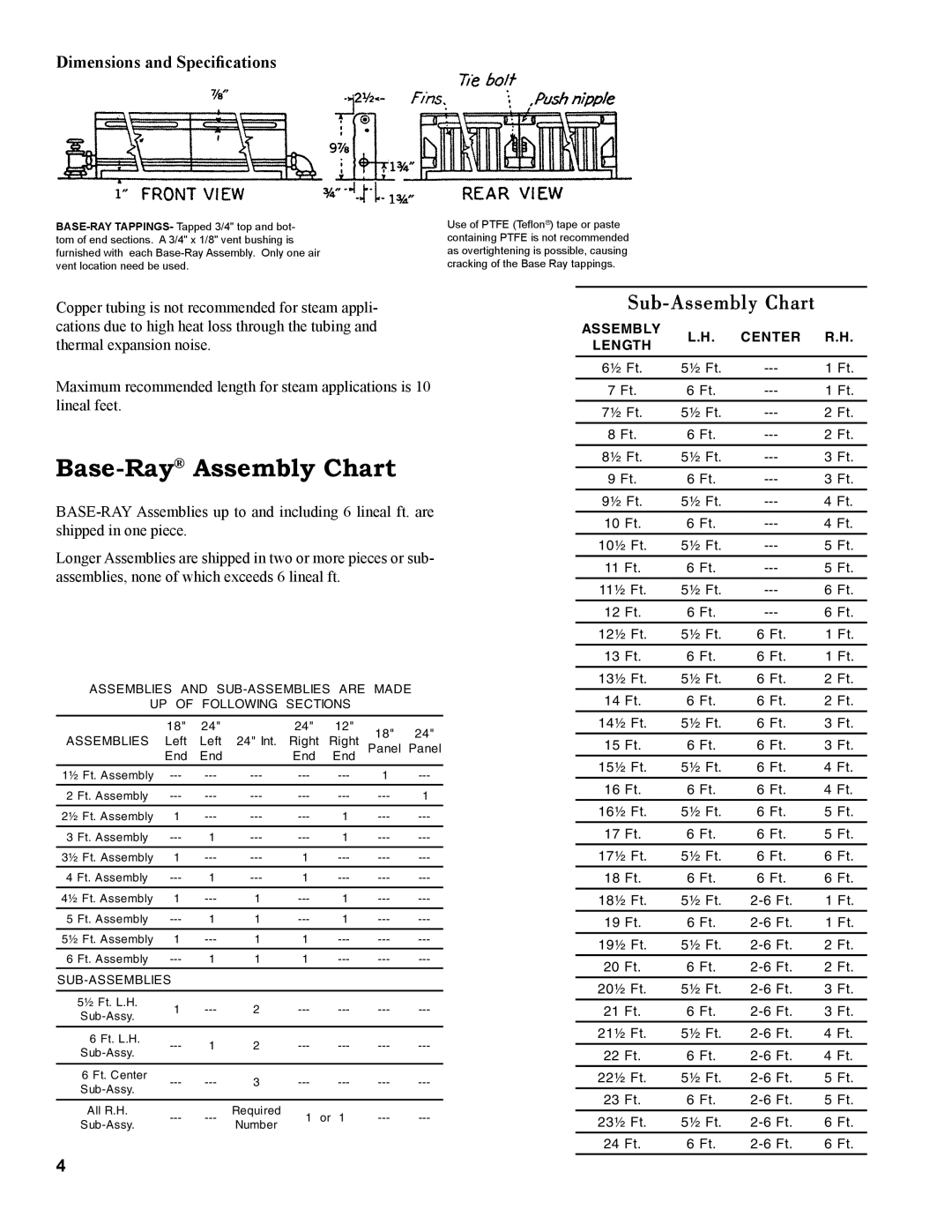
81441001R8-3/06 specifications
The Burnham 81441001R8-3/06 is a state-of-the-art boiler designed to provide efficiency and reliability for residential and commercial heating systems. This model stands out due to its commitment to innovation and advanced engineering, making it a top choice for those seeking optimal heating performance.One of the primary features of the Burnham 81441001R8-3/06 is its high efficiency rating. It is designed to convert fuel into heat with minimal wastage, ensuring that users receive more heat per unit of fuel consumed. This efficiency translates into lower operating costs and a reduced environmental footprint, making it an eco-friendly alternative in the world of heating solutions.
In terms of technology, the Burnham 81441001R8-3/06 is equipped with a robust, cast-iron heat exchanger. This component is crucial for transferring heat effectively while maintaining durability over time. Cast iron is known for its excellent heat retention properties and ability to withstand extreme temperatures, ensuring a longer lifespan for the boiler.
The model also features a user-friendly digital control system that allows for easy operation and monitoring. Homeowners can adjust settings, check system performance, and receive alerts when maintenance is required, leading to prolonged efficiency and safety. The boiler’s compatibility with smart home systems enhances convenience, allowing users to manage heating remotely via smartphones or tablets.
Another characteristic of the Burnham 81441001R8-3/06 is its compact design. This feature makes it ideal for installations in tight spaces without compromising on performance. The unit can fit comfortably in basements, utility rooms, or other restricted areas while delivering powerful heating service.
Moreover, safety is a top priority in the design of the Burnham 81441001R8-3/06. It includes multiple safety features such as pressure relief valves and electronic ignition systems that reduce the risk of accidents. These measures provide peace of mind for homeowners and ensure that the boiler operates safely throughout its lifespan.
In conclusion, the Burnham 81441001R8-3/06 boiler combines high efficiency, durable construction, advanced technology, and safety features, making it a leading choice for those in the market for reliable heating solutions. Whether for residential or commercial applications, it effectively meets the diverse heating needs of users, providing comfort and efficiency for years to come.

