the sight glass using the two ½” tappings to the right of the probe LWCO.

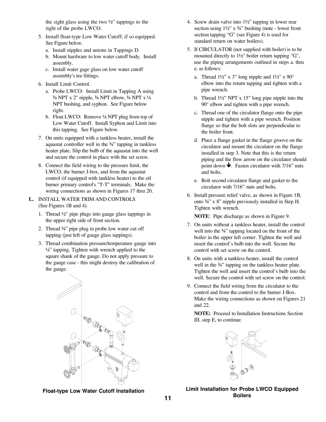
5.Install float-type Low Water Cutoff, if so equipped. See Figure below.

a.Install nipples and unions in Tappings D.

b.Mount hardware to low water cutoff body. Install assembly.

c.Install water gage glass on low water cutoff assembly's tee fittings.

6.Install Limit Control.

a.Probe LWCO: Install Limit in Tapping A using ¾ NPT x 2" nipple, ¾ NPT elbow, ¾ NPT x ¼ NPT bushing, and syphon. See Figure below right.

b.Float LWCO: Remove ¼ NPT plug from top of Low Water Cutoff. Install Syphon and Limit into this tapping. See Figure below.

7.On units equipped with a tankless heater, install the aquastat controller well in the ¾” tapping in tankless heater plate. Slip the bulb of the aquastat into the well and secure the control in place with the set screw.

8.Connect the field wiring to the pressure limit, the LWCO, the burner J-box, and from the aquastat control (if equipped with tankless heater) to the oil burner primary control's "T-T" terminals. Make the wiring connections as shown in Figures 17 thru 20.

L.INSTALL WATER TRIM AND CONTROLS (See Figures 1B and 4).

1.Thread ½” pipe plugs into gauge glass tappings in the upper right side of front section.

2.Thread ¾” pipe plug in probe low water cut off tapping (just left of gauge glass tappings).

3.Thread combination pressure/temperature gauge into ¼” tapping. Tighten with wrench applied to the square shank of the gauge. Do not apply pressure to the gauge case - this might destroy the calibration of the gauge.

4.Screw drain valve into 1½” tapping in lower rear section using 1½” x ¾” bushing (note - lower front section tapping “G” (see Figure 4) is used for standard return on water boilers).

5.If CIRCULATOR (not supplied with boiler) is to be mounted directly to 1½" boiler return tapping "G", use the piping arrangements outlined in steps a. thru e. as follows:

a.Thread 1½” x 3” long nipple and 1½” x 90° elbow into the return tapping and tighten with a pipe wrench.

b.Thread 1½” NPT x 15” long pipe nipple into the 90° elbow and tighten with a pipe wrench.

c.Thread one of the circulator flange onto the pipe nipple and tighten with a pipe wrench. Position flange so that the bolt slots are perpendicular to the boiler front.

d.Place a flange gasket in the flange groove on the circulator and mount the circulator on the flange installed in step 3. Note that this is the return

piping and the flow arrow on the circulator should point down ê. Fasten circulator with 7/16” nuts

and bolts.

e.Bolt second circulator flange and gasket to the circulator with 7/16” nuts and bolts.

6.Install pressure relief valve, as shown in Figure 1B, onto ¾” x 8” nipple previously installed in Step H. Tighten with wrench.

NOTE: Pipe discharge as shown in Figure 9.

7.On units without a tankless heater, install the control well into the ¾” tapping located on the front of the boiler in the upper left corner. Tighten the well and insert the control’s bulb into the well. Secure the control with set screw on the control.

8.On units with a tankless heater, install the control well in the ¾” tapping on the tankless heater plate. Tighten the well and insert the control’s bulb into the well. Secure the control with set screw on the control.

9.Connect the field wiring from the circulator to the control and from the control to the burner J-Box. Make the wiring connections as shown on Figures 21 and 22.

NOTE: Proceed to Installation Instructions Section III, step E, to continue.

Float-type Low Water Cutoff Installation


Limit Installation for Probe LWCO Equipped


Boilers


11


Page 11
Image 11
Burnham V7 SERIES manual

V7 SERIES specifications

The Burnham V7 Series is a standout choice in the realm of residential and light commercial boilers, known for its high efficiency and dependable performance. Engineered for those seeking a reliable heating solution, the V7 Series integrates advanced technologies that prioritize both effectiveness and energy conservation.

At the heart of the Burnham V7 Series is its innovative design that utilizes a cast iron heat exchanger. This robust component ensures excellent durability and longevity while providing efficient heat transfer. The V7's heat exchanger is designed to maximize heating output while minimizing fuel consumption, making it an environmentally friendly option that can help reduce utility costs.

One of the key features of the V7 Series is its ability to operate on multiple fuel sources, including natural gas and propane. This versatility allows homeowners and businesses to choose the most suitable and cost-effective fuel option for their specific needs. The V7 also supports a variety of installation configurations, which makes it adaptable to different spaces and configurations.

The series is equipped with advanced control technologies, including a state-of-the-art electronic ignition system. This system enhances reliability by ensuring a quick and safe start-up while reducing energy waste. Additionally, the integrated boiler control allows users to monitor and adjust their heating settings easily, providing enhanced comfort and efficiency at the touch of a button.

Safety is a top priority in the Burnham V7 Series, which features built-in safety controls to minimize risks. These include thermal overload protection, a pressure relief valve, and a low water cutoff feature, all of which work together to safeguard the boiler and its surroundings.

Moreover, the Burnham V7 Series is designed with a user-friendly interface that makes maintenance straightforward. Routine tasks can be conducted with ease, helping to extend the life of the unit.

In conclusion, the Burnham V7 Series is crafted for those who prioritize efficiency, adaptability, and safety in their heating solutions. With its myriad features and commitment to energy conservation, it stands as a leading choice for heating needs in various settings. The combination of innovative technology, reliable performance, and user-friendly design makes the V7 Series an excellent investment in comfort and efficiency.