V9 Series Piping Recommendations
Water and Steam
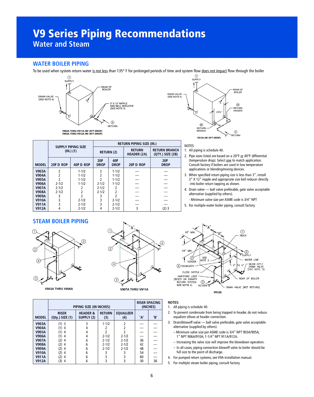
WATeR BOILeR pIpInG
To be used when system return water is not less than 135° F for prolonged periods of time and system flow does not impact flow through the boiler
| SUppLy pIpInG SIZe |
| ReTURn pIpInG SIZe (In.) | |||
|
|
|
|
| ||
|
|
| ReTURn | ReTURn BRAnCH | ||
| (In.) (1) | ReTURn (2) | ||||
|
|
| HeADeR (2A) | (QTy.) SIZe (2B) | ||
|
|
|
|
| ||
MODeL |
|
| 20¡F | 40¡F |
| 20¡F |
20¡F D ROp | 40¡F D ROp | DROp | DROp | 20¡F D ROp | DROp | |
|
|
|
|
|
|
|
V903A | 2 | 2 | Ñ | Ñ | ||
V904A | 2 | 2 | Ñ | Ñ | ||
V905A | 2 | 2 | Ñ | Ñ | ||
V906A | Ñ | Ñ | ||||
V907A | 2 | 2 | Ñ | Ñ | ||
V908A | 2 | 2 | Ñ | Ñ | ||
V909A | 3 | 2 | 3 | 2 | Ñ | Ñ |
V910A | 3 | 3 | Ñ | Ñ | ||
V911A | 3 | 3 | Ñ | Ñ | ||
V912A | 4 | 4 | 3 | (2) 3 | ||
|
|
|
|
|
|
|
NOTES:
1.All piping is schedule 40.
2.Pipe sizes listed are based on a 20°F or 40°F differential
(temperature drop). Select one to match application. Consult factory if boilers are used in low temperature applications or blending/mixing devices.
3.When specified return piping size is less than 3”, install 3” X 12” nipple and appropriate size bell reducer directly into boiler return tapping as shown.
4.Drain valve — ball valve preferable, gate valve acceptable alternative (supplied by others).
- Minimum valve size per ASME code is 3/4” NPT
5.For multiple water boiler piping, consult factory.
STeAM BOILeR pIpInG
|
|
|
|
|
|
| RISeR SpACInG | |
|
|
| pIpInG SIZe (In InCHeS) |
| (InCHeS) | |||
|
|
|
|
|
|
|
| |
| RISeR |
| HeADeR & | ReTURn | eQUALIZeR |
|
| |
MODeL | (Qty.) SIZe (1) |
| SUppLy (2) | (3) | (4) | 'A' | 'B' | |
|
|
|
|
|
|
|
|
|
V903A | (1) | 3 |
| 3 | 2 | Ñ | Ñ | |
V904A | (1) | 4 |
| 4 | 2 | 2 | Ñ | Ñ |
V905A | (1) | 4 |
| 4 | 2 | 2 | Ñ | Ñ |
V906A | (1) | 4 |
| 4 | Ñ | Ñ | ||
V907A | (2) | 4 |
| 6 | 36 | Ñ | ||
V908A | (2) | 4 |
| 6 | 42 | Ñ | ||
V909A | (2) | 4 |
| 6 | 48 | Ñ | ||
V910A | (2) | 4 |
| 6 | 3 | 3 | 54 | Ñ |
V911A | (2) | 4 |
| 6 | 3 | 3 | 60 | Ñ |
V912A | (3) | 4 |
| 6 | 3 | 3 | 30 | 36 |
|
|
|
|
|
|
|
|
|
nOTeS:
1.All piping is schedule 40.
2.To prevent condensate from being trapped in header, do not reduce equalizer elbow at header connection.
3.Drain/blowoff valve — ball valve preferable, gate valve acceptable alternative (supplied by others).
–Minimum valve size per ASME code is 3/4” NPT 903A/905A; 1” NPT 906A/910A;
ÐIncreasing the valve size will improve the blowdown operation.
ÐIn all cases, piping connection blowoff valve to boiler should be full size to the point of discharge.
4.For pumped return systems, see V9A installation manual.
5.For multiple steam boiler piping, consult factory.
6
