RTS specifications
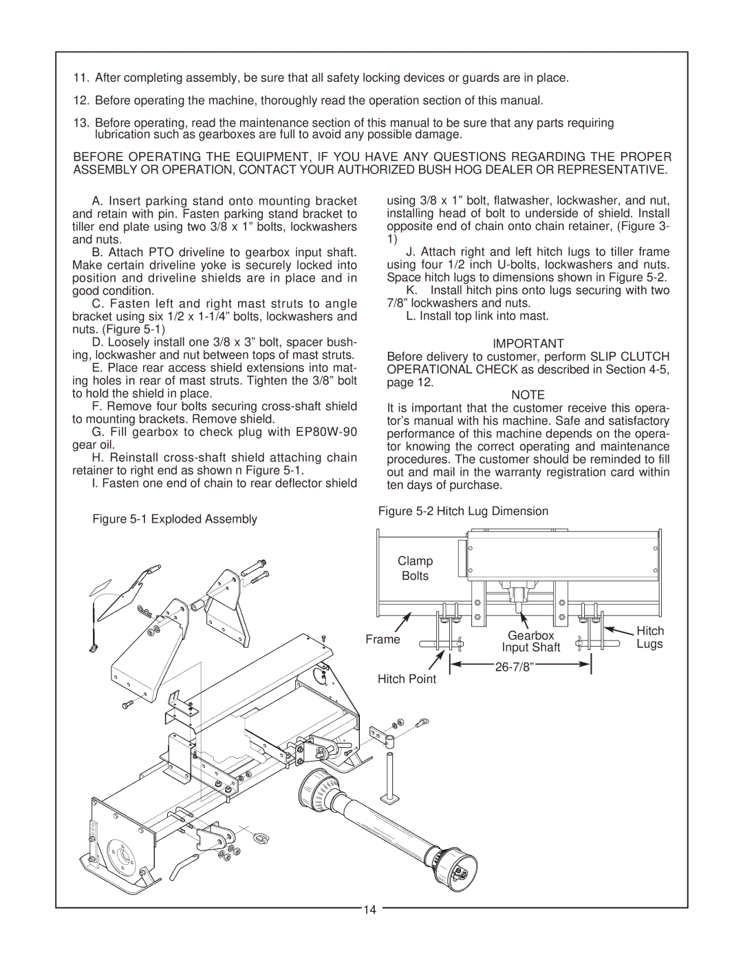
The Bush Hog RTS series is a standout line of rotary tillers designed for both performance and durability, making it an ideal choice for agricultural, landscaping, and gardening applications. Built to meet the demanding needs of professional landscapers and dedicated gardeners, the RTS offers several key features and advanced technologies.One of the most noteworthy aspects of the Bush Hog RTS is its robust construction, which leads to enhanced longevity and reliability. The frame is heavily reinforced to withstand tough operating conditions, while the tiller tines are crafted from high-quality materials, ensuring they maintain their sharpness and effectiveness even after extensive use. This durability translates to lower maintenance costs and reduced downtime, crucial for maintaining productivity.
In terms of performance, the RTS series stands out with its impressive tilling depth and width capabilities. Users can achieve a maximum tilling depth that allows for effective soil aeration, promoting root growth and improving overall soil health. The width options available in the RTS lineup provide flexibility, catering to various field sizes and types of landscaping projects.
The Bush Hog RTS also incorporates advanced technology to enhance ease of use. The adjustable side runners enable users to control the tilling depth precisely, while built-in gearbox systems allow for smooth power transfer, ensuring consistent performance while reducing wear and tear on the machine.
Another significant feature is the chain-driven design that promotes efficient power usage and minimizes slippage. This results in a more reliable operation, especially in challenging soil conditions. Furthermore, the RTS series is compatible with a variety of tractor models, making it a versatile addition to any equipment fleet.
To maximize operator comfort and efficiency, the RTS features an ergonomic design, enabling easy attachment and detachment to tractors. The simple controls and straightforward operation make it accessible for users of all skill levels, reducing the learning curve for new operators.
Overall, the Bush Hog RTS rotary tillers combine strength, versatility, and innovative features, positioning them as a top choice for those looking to enhance their land management and agricultural productivity. With their superior construction and performance, the RTS series stands ready to tackle soil preparation tasks of any scale with ease and effectiveness.

