7. Bringing into operation
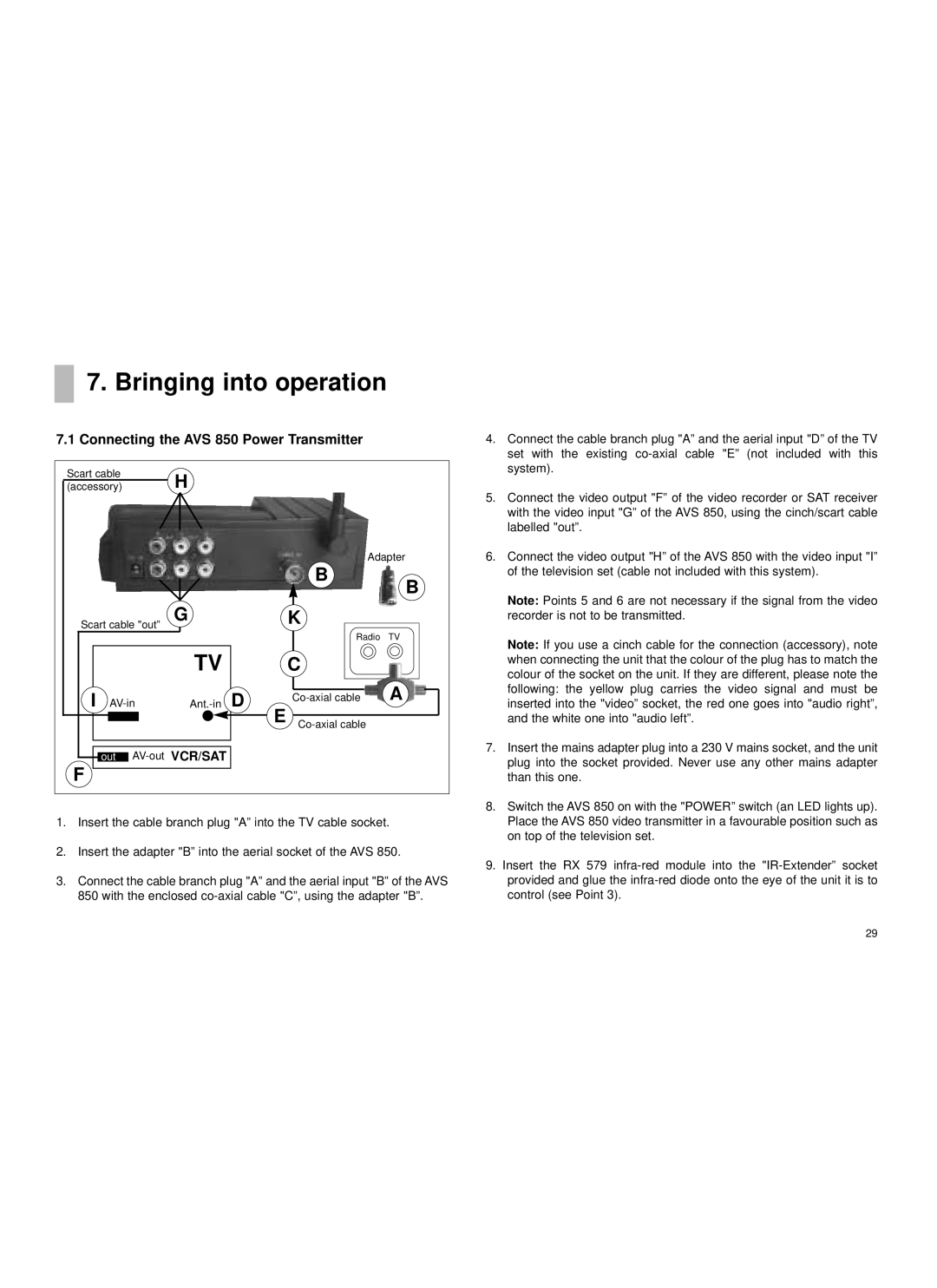
7.1 Connecting the AVS 850 Power Transmitter
Scart cable | H |
|
|
|
(accessory) |
|
|
| |
|
|
|
| Adapter |
|
|
| B | B |
|
|
|
| |
Scart cable "out” | G |
| K |
|
|
|
| Radio TV | |
| TV |
| C |
|
I | D | A | ||
E |
| |||
|
|
|
| |
out |
|
|
| |
F |
|
|
|
|
1.Insert the cable branch plug "A” into the TV cable socket.
2.Insert the adapter "B” into the aerial socket of the AVS 850.
3.Connect the cable branch plug "A” and the aerial input "B” of the AVS 850 with the enclosed
4.Connect the cable branch plug "A” and the aerial input "D” of the TV set with the existing
5.Connect the video output "F” of the video recorder or SAT receiver with the video input "G” of the AVS 850, using the cinch/scart cable labelled "out”.
6.Connect the video output "H” of the AVS 850 with the video input "I” of the television set (cable not included with this system).
Note: Points 5 and 6 are not necessary if the signal from the video recorder is not to be transmitted.
Note: If you use a cinch cable for the connection (accessory), note when connecting the unit that the colour of the plug has to match the colour of the socket on the unit. If they are different, please note the following: the yellow plug carries the video signal and must be inserted into the "video” socket, the red one goes into "audio right”, and the white one into "audio left”.
7.Insert the mains adapter plug into a 230 V mains socket, and the unit plug into the socket provided. Never use any other mains adapter than this one.
8.Switch the AVS 850 on with the "POWER” switch (an LED lights up). Place the AVS 850 video transmitter in a favourable position such as on top of the television set.
9.Insert the RX 579
29