NB25 E, NB20E specifications
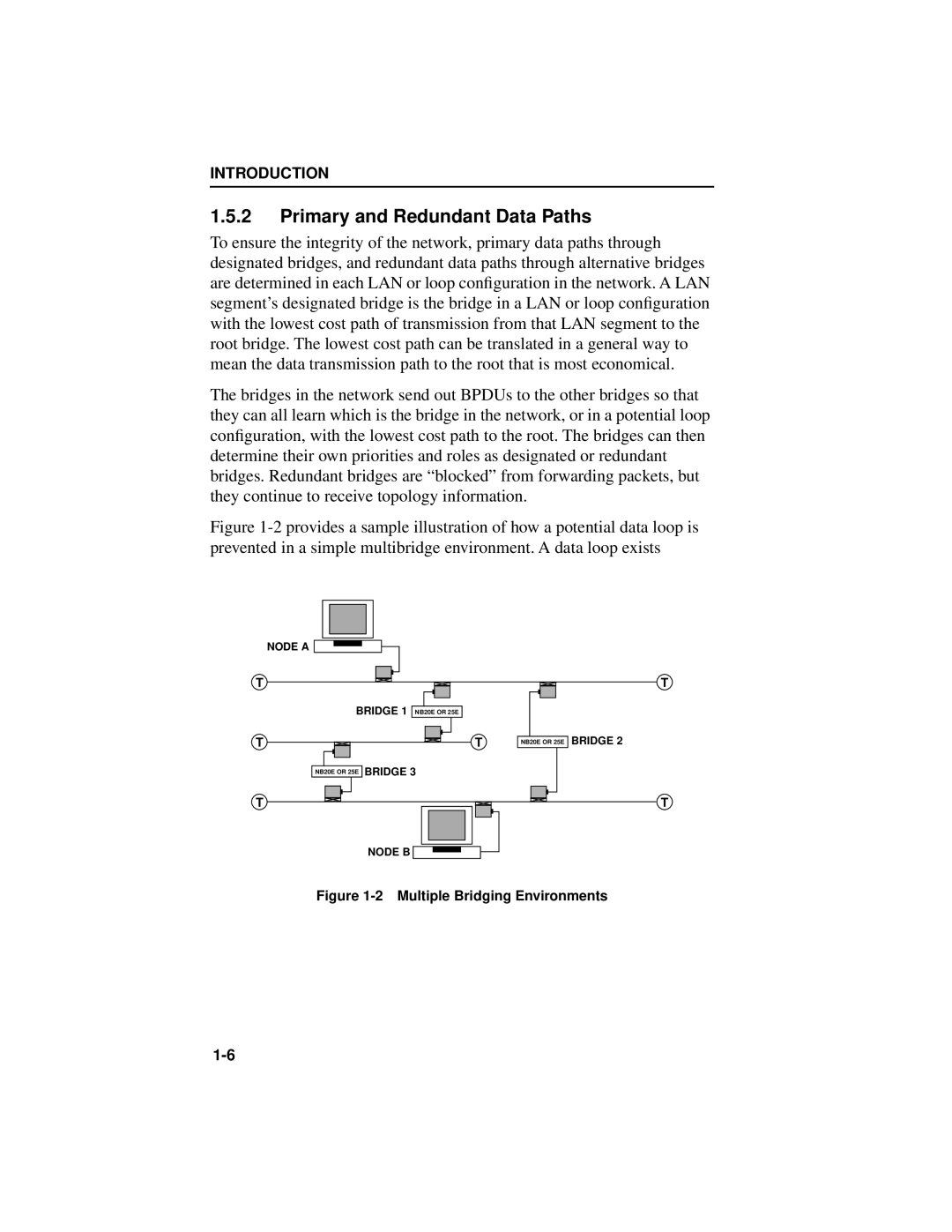
Cabletron Systems, renowned for its innovative networking solutions in the late 20th century, introduced the NB20E and NB25E series, which made a significant impact in the realm of network management and reliability. These devices were tailored for businesses seeking to enhance their network infrastructure with efficiency and reliability.The NB20E is known for its robust performance in medium-sized network environments. It operates with an architecture that allows for seamless integration into existing networks, providing essential features that cater to both versatility and scalability. One of its standout functionalities is the support for multiple protocols, enabling organizations to harness various networking standards without the need for extensive alterations to their current setups.
On the other hand, the NB25E extends these capabilities further, offering enhanced throughput and a more comprehensive range of networking options. This makes it particularly suitable for larger businesses with growing networking demands. The utilization of advanced technologies, such as its embedded intelligence, ensures that the NB25E can efficiently manage and direct network traffic, thus minimizing latency and maintaining optimal performance even during peak usage times.
Both models provide essential characteristics such as a modular design, allowing for easy upgrades and maintenance. This modularity not only prolongs the lifespan of the devices but also provides flexibility for future expansions or modifications as business needs evolve. The systems support various interfaces, catering to diverse environments and ensuring easy connectivity to other networking equipment.
Security is a paramount concern in today’s interconnected world, and Cabletron Systems addressed this in the NB20E and NB25E series. The devices are equipped with advanced security features that protect against unauthorized access and ensure data integrity, providing peace of mind for organizations relying on critical data transmissions.
In addition to their technical advantages, both models offer user-friendly management software, making monitoring and control straightforward even for those with limited networking expertise. This ease of use ensures that companies can leverage their investment fully without requiring extensive training or resources.
In summary, the Cabletron Systems NB20E and NB25E series represent a significant leap in networking technology during their era. With advanced features, modular capabilities, and a commitment to security, these devices remain a noteworthy consideration for businesses looking to enhance their networks and prepare for future growth.

