Manual de Instrucciones y Lista de Piezas
DG411200CK |
Ensamblaje
GUÍA LÁSER
Instalación de las baterías
1.Asegúrese de que el interruptor de la guía láser esté apagado (presionando el “O” en el interruptor oscilante).
2.Usando un destornillador Phillips pequeño, quite el pequeño tornillo de seguridad.
3.Levante la tapa del compartimiento de las baterías con un cuchillo romo en proximidad del hueco del tornillo.
4.Instale dos baterías AAA observando la orientación/polaridad grabada en el compartimiento de las baterías.
5.Vuelva a colocar la tapa del compartimiento de las baterías y apriete suavemente el pequeño tornillo de seguridad.
Ajuste del rayo láser
El rayo láser ha sido preajustado/alineado de fábrica pero, debido al manejo, puede haberse desplazado de su posición preajustada. Para verificar la alineación del rayo láser, primero asegúrese de que el bisel de la sierra esté ajustado a cero
(es decir, la sierra no está en ángulo) y luego encienda el láser por el interruptor. Verifique que el láser esté alineado con la marca del 0° en la parte delantera de la placa base. Si no está alineada con este borde, tome una pinza de punta fina y suavemente sujete la parte de bronce del láser. Gire esta parte hasta que el rayo láser quede alineado con la línea de corte de la base.
CÓMO COLOCAR LA HOJA
Para instalar la hoja
1.Asegúrese de que el interruptor esté en la posición “off” (apagado) y que la sierra esté desconectada de la fuente de energía.
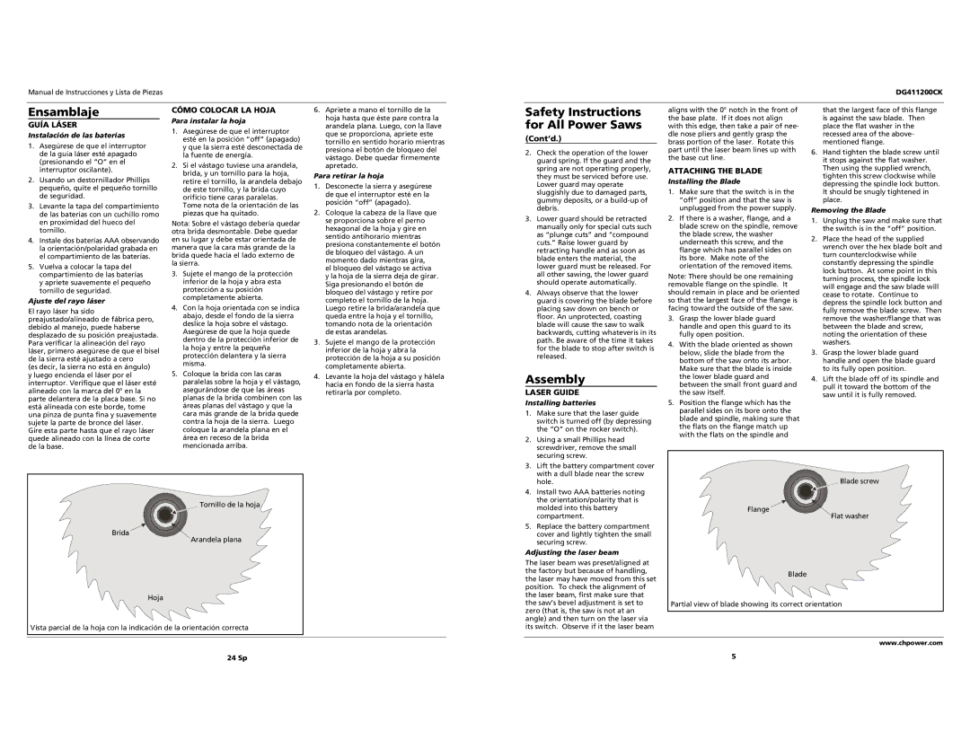
2.Si el vástago tuviese una arandela, brida, y un tornillo para la hoja, retire el tornillo, la arandela debajo de este tornillo, y la brida cuyo orificio tiene caras paralelas.
Tome nota de la orientación de las piezas que ha quitado.
Nota: Sobre el vástago debería quedar otra brida desmontable. Debe quedar en su lugar y debe estar orientada de manera que la cara más grande de la brida quede hacia el lado externo de la sierra.
3.Sujete el mango de la protección inferior de la hoja y abra esta protección a su posición completamente abierta.
4.Con la hoja orientada con se indica abajo, desde el fondo de la sierra deslice la hoja sobre el vástago. Asegúrese de que la hoja quede dentro de la protección inferior de la hoja y entre la pequeña protección delantera y la sierra misma.
5.Coloque la brida con las caras paralelas sobre la hoja y el vástago, asegurándose de que las áreas planas de la brida combinen con las áreas planas del vástago y que la cara más grande de la brida quede contra la hoja de la sierra. Luego coloque la arandela plana en el área en receso de la brida mencionada arriba.
6.Apriete a mano el tornillo de la hoja hasta que éste pare contra la arandela plana. Luego, con la llave que se proporciona, apriete este tornillo en sentido horario mientras presiona el botón de bloqueo del vástago. Debe quedar firmemente apretado.
Para retirar la hoja
1.Desconecte la sierra y asegúrese de que el interruptor esté en la posición “off” (apagado).
2.Coloque la cabeza de la llave que se proporciona sobre el perno hexagonal de la hoja y gire en sentido antihorario mientras presiona constantemente el botón de bloqueo del vástago. A un momento dado mientras gira,
el bloqueo del vástago se activa y la hoja de la sierra deja de girar. Siga presionando el botón de bloqueo del vástago y retire por completo el tornillo de la hoja. Luego retire la brida/arandela que queda entre la hoja y el tornillo, tomando nota de la orientación de estas arandelas.
3.Sujete el mango de la protección inferior de la hoja y abra la protección de la hoja a su posición completamente abierta.
4.Levante la hoja del vástago y hálela hacia en fondo de la sierra hasta retirarla por completo.
Safety Instructions | aligns with the 0° notch in the front of |
| that the largest face of this flange | |
the base plate. If it does not align |
| is against the saw blade. Then | ||
for All Power Saws |
| |||
with this edge, then take a pair of nee- |
| place the flat washer in the | ||
(Cont’d.) | dle nose pliers and gently grasp the |
| recessed area of the above- | |
brass portion of the laser. Rotate this |
| mentioned flange. | ||
|
| |||
2. Check the operation of the lower | part until the laser beam lines up with | 6. | Hand tighten the blade screw until | |
the base cut line. | ||||
guard spring. If the guard and the |
| it stops against the flat washer. | ||
|
| |||
spring are not operating properly, | ATTACHING THE BLADE |
| Then using the supplied wrench, | |
they must be serviced before use. |
| tighten this screw clockwise while | ||
Installing the Blade |
| |||
Lower guard may operate |
| depressing the spindle lock button. | ||
|
| |||
sluggishly due to damaged parts, | 1. Make sure that the switch is in the |
| It should be snugly tightened in | |
gummy deposits, or a | “off” position and that the saw is |
| place. | |
debris. | unplugged from the power supply. | Removing the Blade | ||
3. Lower guard should be retracted | 2. If there is a washer, flange, and a | 1. Unplug the saw and make sure that | ||
manually only for special cuts such | blade screw on the spindle, remove |
| the switch is in the “off” position. | |
as “plunge cuts” and “compound | the blade screw, the washer | 2. Place the head of the supplied | ||
cuts.” Raise lower guard by | underneath this screw, and the | |||
| wrench over the hex blade bolt and | |||
retracting handle and as soon as | flange which has parallel sides on |
| ||
| turn counterclockwise while | |||
blade enters the material, the | its bore. Make note of the |
| ||
| constantly depressing the spindle | |||
lower guard must be released. For | orientation of the removed items. |
| ||
| lock button. At some point in this | |||
all other sawing, the lower guard | Note: There should be one remaining |
| ||
| turning process, the spindle lock | |||
should operate automatically. | removable flange on the spindle. It |
| ||
| will engage and the saw blade will | |||
4. Always observe that the lower | should remain in place and be oriented |
| ||
| cease to rotate. Continue to | |||
guard is covering the blade before | so that the largest face of the flange is |
| depress the spindle lock button and | |
placing saw down on bench or | facing toward the outside of the saw. |
| fully remove the blade screw. Then | |
floor. An unprotected, coasting | 3. Grasp the lower blade guard |
| remove the washer/flange that was | |
blade will cause the saw to walk | handle and open this guard to its |
| between the blade and screw, | |
backwards, cutting whateveris in its | fully open position. |
| noting the orientation of these | |
path. Be aware of the time it takes | 4. With the blade oriented as shown |
| washers. | |
for the blade to stop after switch is | 3. | Grasp the lower blade guard | ||
below, slide the blade from the | ||||
released. | ||||
bottom of the saw onto its arbor. |
| handle and open the blade guard | ||
|
| |||
Assembly | Make sure that the blade is inside |
| to its fully open position. | |
the lower blade guard and | 4. | Lift the blade off of its spindle and | ||
between the small front guard and | ||||
|
| pull it toward the bottom of the | ||
LASER GUIDE |
| |||
the saw itself. |
| |||
| saw until it is fully removed. | |||
Installing batteries | 5. Position the flange which has the | ||
1. | Make sure that the laser guide | parallel sides on its bore onto the | |
blade and spindle, making sure that | |||
| switch is turned off (by depressing | ||
| the flats on the flange match up | ||
| the “O” on the rocker switch). | ||
| with the flats on the spindle and | ||
2. | Using a small Phillips head | ||
| |||
| screwdriver, remove the small |
| |
| securing screw. |
| |
3. | Lift the battery compartment cover |
| |
| with a dull blade near the screw |
| |
Tornillo de la hoja |
Brida |
Arandela plana |
Hoja |
Vista parcial de la hoja con la indicación de la orientación correcta |
24 Sp
hole. |
|
|
| Blade screw | ||||||
4. Install two AAA batteries noting |
|
|
|
|
|
|
|
|
|
|
|
|
|
|
|
|
|
|
|
| |
the orientation/polarity that is |
|
|
|
|
|
|
|
|
|
|
molded into this battery |
| Flange |
|
|
|
|
|
|
|
|
|
|
| ||||||||
compartment. |
|
|
| Flat washer | ||||||
5. Replace the battery compartment |
|
|
|
|
|
|
|
|
|
|
cover and lightly tighten the small |
|
|
|
|
|
|
|
|
|
|
securing screw. |
|
|
|
|
|
|
|
|
|
|
|
|
|
|
|
|
|
|
|
| |
Adjusting the laser beam |
|
|
|
|
|
|
|
|
|
|
|
|
|
|
|
|
|
|
|
| |
The laser beam was preset/aligned at |
|
|
|
|
|
|
|
|
|
|
the factory but because of handling, |
|
|
|
|
|
|
|
|
|
|
| Blade | |||||||||
the laser may have moved from this set |
| |||||||||
|
|
|
|
|
|
|
|
|
| |
position. To check the alignment of |
|
|
|
|
|
|
|
|
|
|
the laser beam, first make sure that |
|
|
|
|
|
|
|
|
|
|
the saw’s bevel adjustment is set to | Partial view of blade showing its correct orientation | |||||||||
zero (that is, the saw is not at an |
|
|
|
|
|
|
|
|
|
|
|
|
|
|
|
|
|
|
|
| |
angle) and then turn on the laser via |
|
|
|
|
|
|
|
|
|
|
its switch. Observe if it the laser beam |
|
|
|
|
|
|
|
|
|
|
|
|
|
|
|
|
|
|
|
|
|
|
|
|
|
|
|
|
| www.chpower.com | ||
| 5 |
|
|
|
|
|
|
|
| |