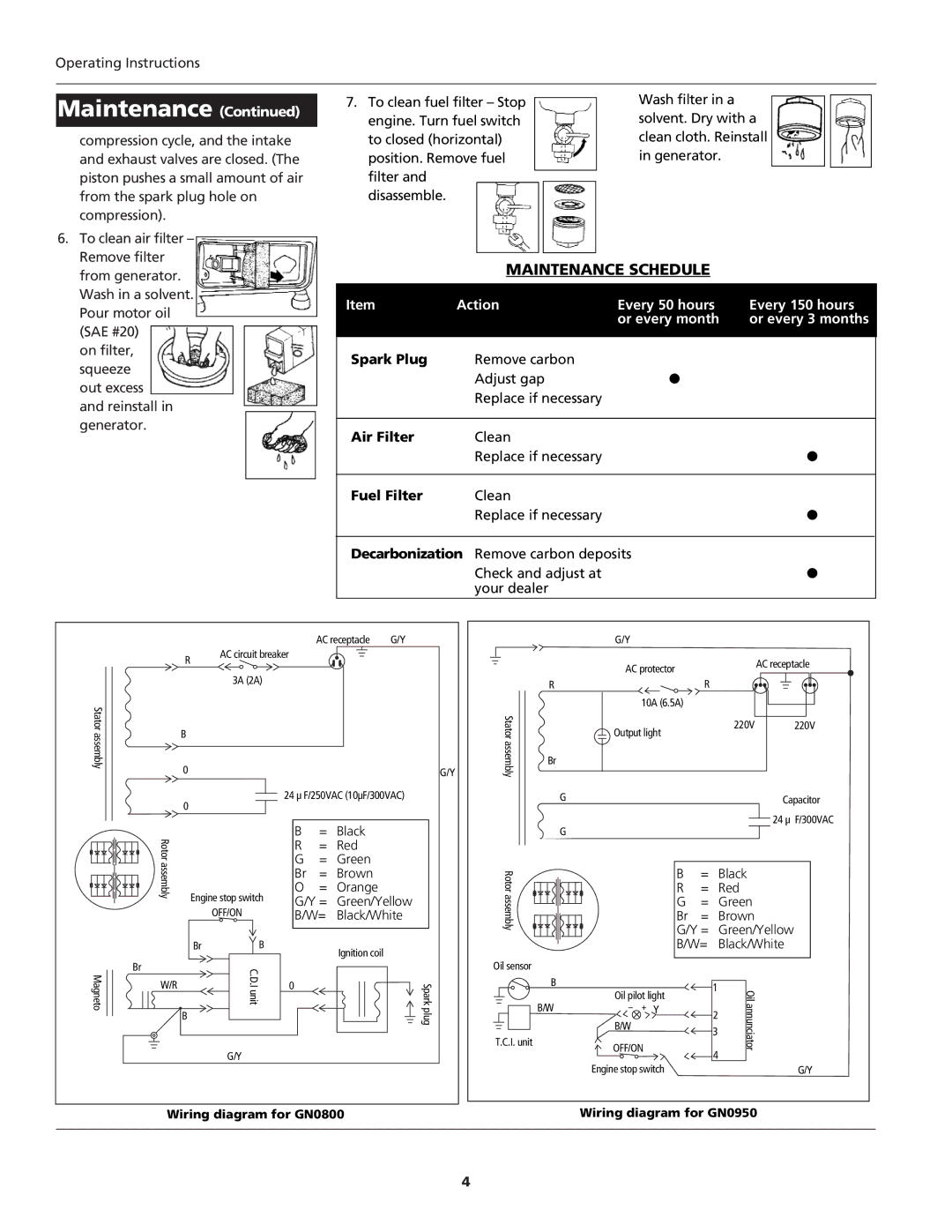
GN0800, GN0950 specifications
The Campbell Hausfeld GN0800 and GN0950 are powerful and efficient air compressors designed to cater to the needs of both DIY enthusiasts and professional users alike. Known for their durability and performance, these models are equipped with features that make them stand out in a crowded market.The GN0800 is a 1.0 HP, 8-gallon air compressor, providing ample airflow for a variety of tasks such as inflating tires, powering pneumatic tools, and spraying paint. Its oil-free pump offers a maintenance-free experience, meaning users can focus on their projects without the hassle of oil changes. The GN0800 also features a quick recovery time; with a maximum pressure of 125 PSI, it can quickly recharge, allowing for continuous use in demanding applications.
On the other hand, the GN0950 comes with a more robust configuration. This model is designed to tackle tougher jobs and heavy-duty applications. It boasts a 2.0 HP motor and a large 9-gallon tank, enabling it to store more air, which lends to longer run times without frequent cycling. The GN0950 can reach up to 145 PSI, providing even higher pressure for more demanding tasks, making it suitable for a wide range of industrial and construction applications.
Both models feature a compact design and lightweight construction, making them easily portable. They come equipped with conveniently placed handles and wheels, which enhance mobility around job sites or workshops. Additionally, these compressors feature multiple outlet ports, allowing users to connect various tools simultaneously, improving productivity and efficiency.
In terms of safety, the Campbell Hausfeld GN series is designed with user protection in mind. They include thermal overload protection, which prevents the motor from overheating, extending the life of the compressor.
Another important aspect is their noise level. Both the GN0800 and GN0950 are designed to operate quietly, allowing users to work comfortably without excessive noise disrupting their tasks.
In summary, the Campbell Hausfeld GN0800 and GN0950 are reliable air compressors that offer excellent performance, durability, and features that cater to versatile applications, making them an excellent investment for anyone looking to undertake air-powered tasks effectively.

