Operating Instructions and Parts Manual
Assembly
Tools Required for Assembly
uRatchet with 3/8 inch Socket
u(2) Wrenches
Handle Assembly
1.Slide handle into shroud holes, making sure handle is on the outside of the bracket and the holes of the handle line up with the holes of the tank bracket.
2.Insert screws through handle and then the bracket. Using a ratchet with 3/8 inch socket, tighten screws to hold the handle in place.
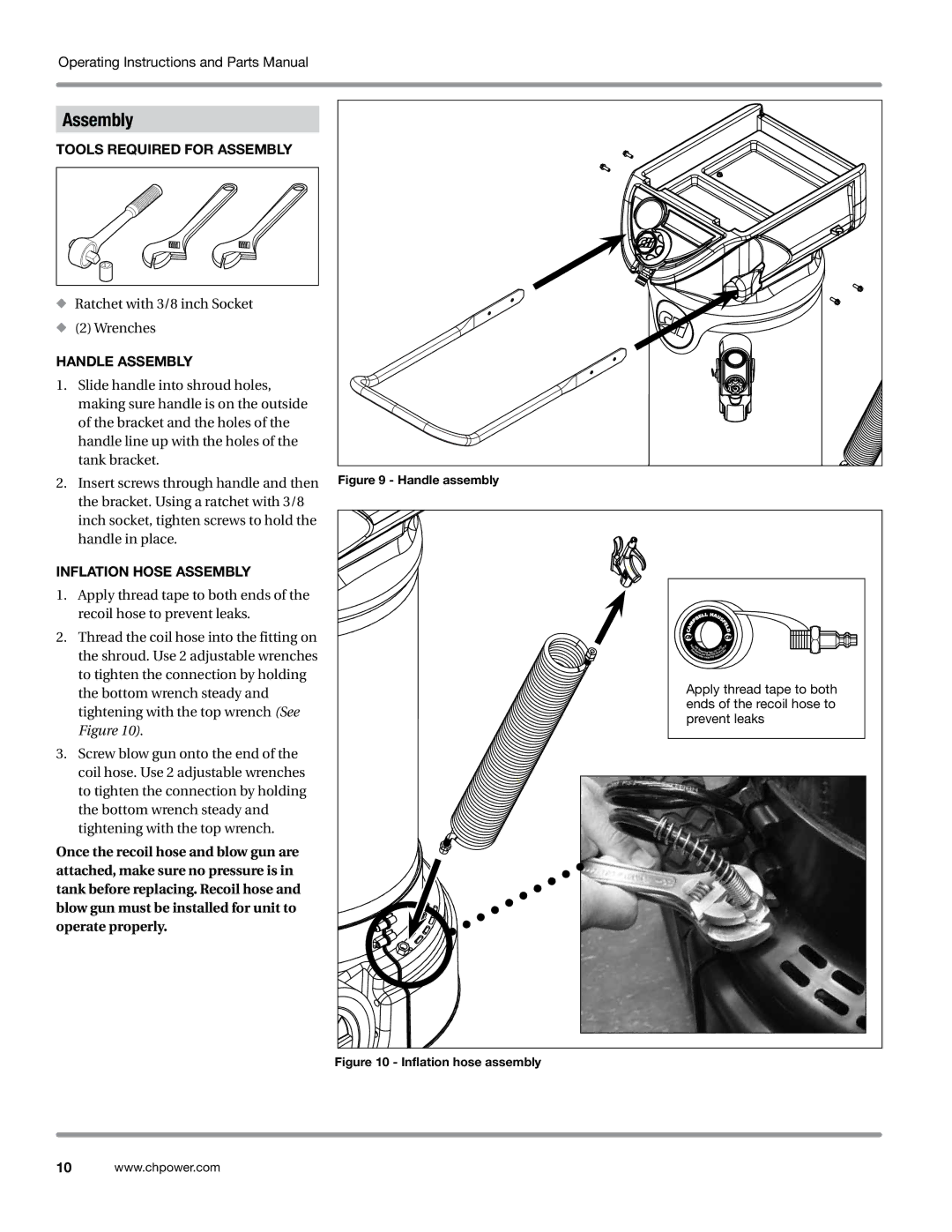
Inflation Hose Assembly
1.Apply thread tape to both ends of the recoil hose to prevent leaks.
2.Thread the coil hose into the fitting on the shroud. Use 2 adjustable wrenches to tighten the connection by holding the bottom wrench steady and tightening with the top wrench (See Figure 10).
3.Screw blow gun onto the end of the coil hose. Use 2 adjustable wrenches to tighten the connection by holding the bottom wrench steady and tightening with the top wrench.
Once the recoil hose and blow gun are attached, make sure no pressure is in tank before replacing. Recoil hose and blow gun must be installed for unit to operate properly.
Figure 9 - Handle assembly
Apply thread tape to both ends of the recoil hose to prevent leaks
Figure 10 - Inflation hose assembly
10www.chpower.com