WL6700 Series
Installation
Location
When assembled, the tank must sit level to allow the tank to drain properly.
It is extremely important to install the compressor in a clean, well ventilated area where the surrounding air temperature will not be more than 100°F.
A minimum clearance of 18 inches between the compressor and a wall is required because objects could obstruct air flow.
Do not locate the compressor air inlet near steam, paint spray, sandblast areas or any other source of contamination. This debris will damage the motor.
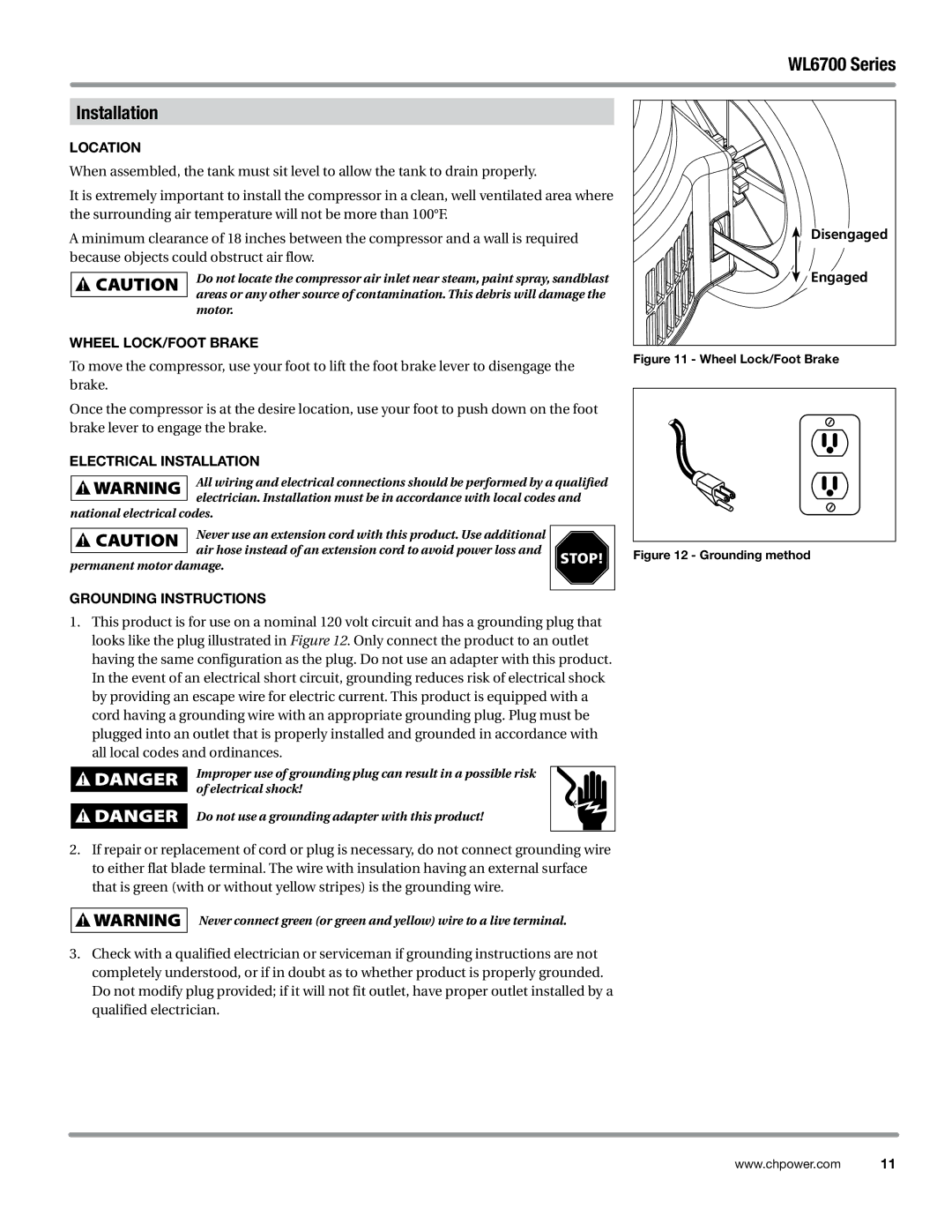
Wheel Lock/Foot Brake
To move the compressor, use your foot to lift the foot brake lever to disengage the brake.
Once the compressor is at the desire location, use your foot to push down on the foot brake lever to engage the brake.
Electrical Installation
All wiring and electrical connections should be performed by a qualified electrician. Installation must be in accordance with local codes and
national electrical codes.
Never use an extension cord with this product. Use additional |
| |
air hose instead of an extension cord to avoid power loss and | STOP! | |
permanent motor damage. | ||
| ||
Grounding Instructions |
|
1.This product is for use on a nominal 120 volt circuit and has a grounding plug that looks like the plug illustrated in Figure 12. Only connect the product to an outlet having the same configuration as the plug. Do not use an adapter with this product. In the event of an electrical short circuit, grounding reduces risk of electrical shock by providing an escape wire for electric current. This product is equipped with a cord having a grounding wire with an appropriate grounding plug. Plug must be plugged into an outlet that is properly installed and grounded in accordance with all local codes and ordinances.
Improper use of grounding plug can result in a possible risk of electrical shock!
Do not use a grounding adapter with this product!
2.If repair or replacement of cord or plug is necessary, do not connect grounding wire to either flat blade terminal. The wire with insulation having an external surface that is green (with or without yellow stripes) is the grounding wire.
Never connect green (or green and yellow) wire to a live terminal.
3.Check with a qualified electrician or serviceman if grounding instructions are not completely understood, or if in doubt as to whether product is properly grounded. Do not modify plug provided; if it will not fit outlet, have proper outlet installed by a qualified electrician.
Disengaged |
Engaged |
Figure 11 - Wheel Lock/Foot Brake
Figure 12 - Grounding method
www.chpower.com 11