1. Introduction
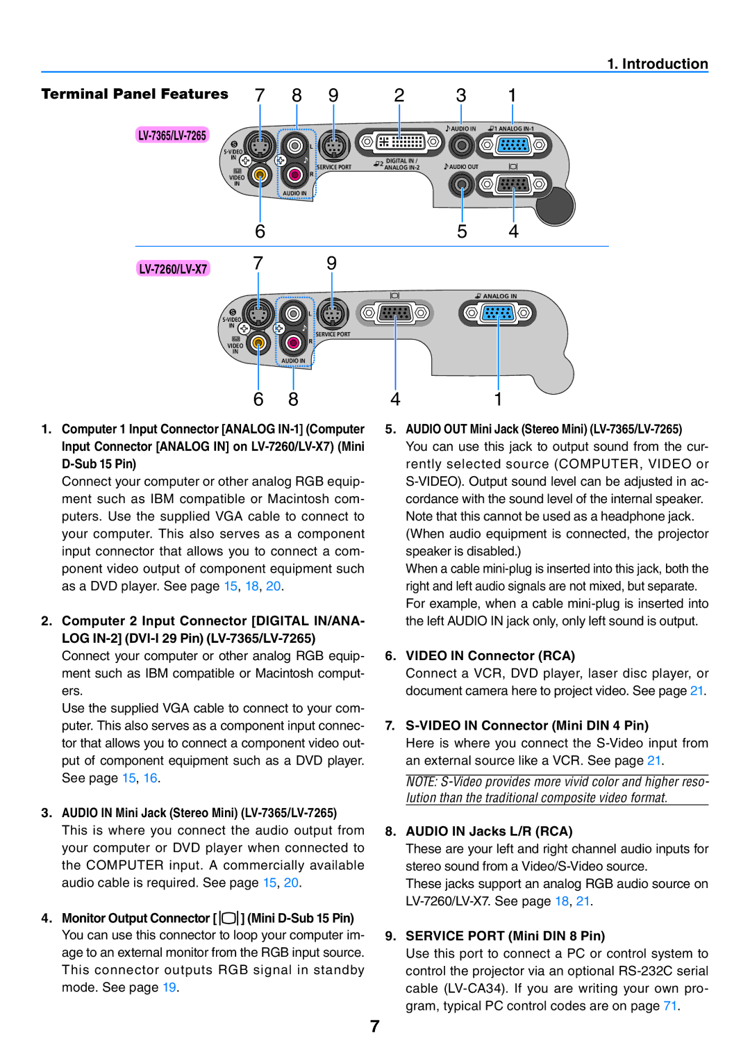
Terminal Panel Features 7 8 9 | 2 | 3 | 1 |
LV-7365/LV-7265
AUDIO IN | ANALOG |
| L |
|
|
| |
|
|
|
|
| |
| IN |
| DIGITAL IN / |
|
|
|
| SERVICE PORT | AUDIO OUT |
| |
|
| ANALOG |
| ||
| VIDEO | R |
|
|
|
|
|
|
|
| |
| IN |
|
|
|
|
|
| AUDIO IN |
|
|
|
| 6 |
|
| 5 | 4 |
7 | 9 |
|
|
| |
|
|
|
|
| ANALOG IN |
| L |
|
|
| |
|
|
|
|
| |
| IN |
|
|
|
|
|
| SERVICE PORT |
|
|
|
| VIDEO | R |
|
|
|
|
|
|
|
| |
| IN |
|
|
|
|
|
| AUDIO IN |
|
|
|
| 6 | 8 | 4 |
| 1 |
1.Computer 1 Input Connector [ANALOG
Connect your computer or other analog RGB equip- ment such as IBM compatible or Macintosh com- puters. Use the supplied VGA cable to connect to your computer. This also serves as a component input connector that allows you to connect a com- ponent video output of component equipment such as a DVD player. See page 15, 18, 20.
2.Computer 2 Input Connector [DIGITAL IN/ANA- LOG
5.AUDIO OUT Mini Jack (Stereo Mini)
When a cable
Connect your computer or other analog RGB equip- | 6. | VIDEO IN Connector (RCA) | |
ment such as IBM compatible or Macintosh comput- |
| Connect a VCR, DVD player, laser disc player, or | |
ers. |
| document camera here to project video. See page 21. | |
Use the supplied VGA cable to connect to your com- |
|
|
|
puter. This also serves as a component input connec- | 7. |
| |
tor that allows you to connect a component video out- |
| Here is where you connect the | |
put of component equipment such as a DVD player. |
| an external source like a VCR. See page 21. | |
See page 15, 16. |
|
|
|
| NOTE: | ||
|
| lution than the traditional composite video format. | |
3. AUDIO IN Mini Jack (Stereo Mini) (LV-7365/LV-7265)
This is where you connect the audio output from your computer or DVD player when connected to the COMPUTER input. A commercially available audio cable is required. See page 15, 20.
4.Monitor Output Connector [ ![]()
![]() ] (Mini
] (Mini
8.AUDIO IN Jacks L/R (RCA)
These are your left and right channel audio inputs for stereo sound from a
These jacks support an analog RGB audio source on
9.SERVICE PORT (Mini DIN 8 Pin)
Use this port to connect a PC or control system to control the projector via an optional