Connection Diagrams
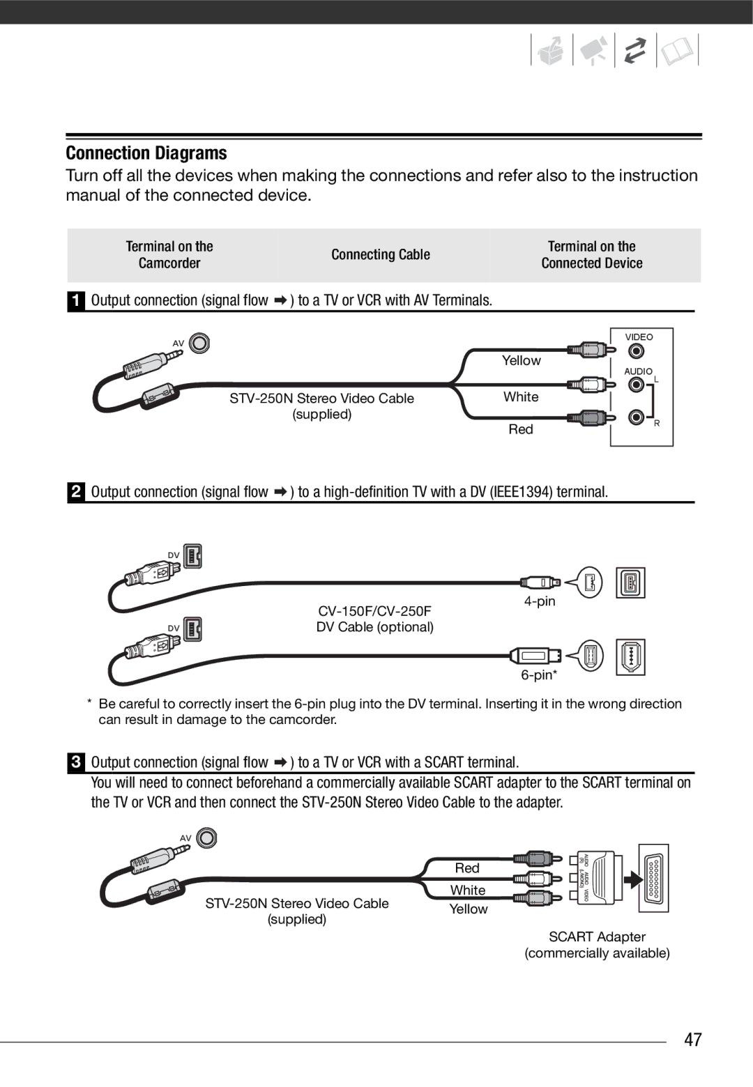
Turn off all the devices when making the connections and refer also to the instruction manual of the connected device.
Terminal on the | Connecting Cable | Terminal on the | |
Camcorder | Connected Device | ||
| |||
|
|
|
1
Output connection (signal flow ![]() ) to a TV or VCR with AV Terminals.
) to a TV or VCR with AV Terminals.
| Yellow | |
|
| |
White | ||
(supplied) | Red | |
| ||
VIDEO
AUDIO
L
R
2
Output connection (signal flow ![]() ) to a
) to a
DV Cable (optional)
*Be careful to correctly insert the
3Output connection (signal flow ![]() ) to a TV or VCR with a SCART terminal.
) to a TV or VCR with a SCART terminal.
You will need to connect beforehand a commercially available SCART adapter to the SCART terminal on the TV or VCR and then connect the
| Red | |
White | ||
Yellow | ||
(supplied) | ||
|
SCART Adapter
(commercially available)
47