INSTALL BALL AND SOLENOID VALVES Ð Using good piping practice, braze ball valve and solenoid valve into
IMPORTANT: When installing solenoid valve, make sure that ¯ow direction arrow on valve body points towards the cooler. The minimum load control will not function correctly if this valve is installed backwards.
CONNECT PIPING Ð Check the ends of the tubes where they will be inserted into the Swagelok ®ttings. To avoid leaks, tube ends must be round and free of burrs, nicks, and grooves.
Insert tube ends into ®ttings as far as they will go. When tube bottoms out, tighten the compression nut
IMPORTANT: Do NOT overtighten the ®ttings. Over- tightening the ®ttings can deform the tube ends and cause leaks.
30GX UNITS ONLY Ð Using good brazing practice, braze the
Step 3 Ð Dehydrate and Recharge Circuit
ÐWhen piping has been completed, leak test the assem- bly. If one of the Swagelok ®ttings leaks, slowly tighten the compression nut until the leak stops. If this does not ®x the leak, the connection must be reinstalled using a new ferrule and backup ring in the ®tting. Contact your Carrier repre- sentative for assistance in locating these parts.
After leak testing, evacuate, dehydrate, and recharge the circuit using an approved refrigerant recovery device. Cor- rect type and amount of refrigerant are listed on unit name- plate and in base unit documentation.
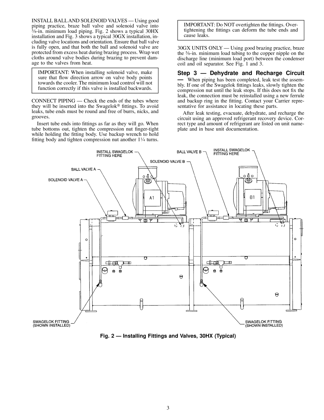
Fig. 2 Ð Installing Fittings and Valves, 30HX (Typical)
3