Step 4 Ð Install Control Wiring
Be sure all power to the unit is off before proceeding. Lock out and safety-tag all disconnects.
Wires between ®eld-installed components and unit control box must be enclosed in ®eld-supplied conduit. Follow all local codes and NEC (National Electrical Code, U.S.A.). Wire size must be no. 16 AWG (American Wire Gage) (1.5 mm2) minimum. See Fig. 4 for ®eld wiring.
30HX UNITS Ð Remove the screws holding the right-side access panel to the unit control box. Remove the right-side access panel and store in a safe area.
Route wires through ®eld-supplied conduit and attach the conduit to the unit control box, using a suitable conduit ®t- ting and one of the available 7¤8-in. knockout openings. At- tach the other end of the conduit to the solenoid valve, using a suitable ®tting. Repeat for the other circuit.
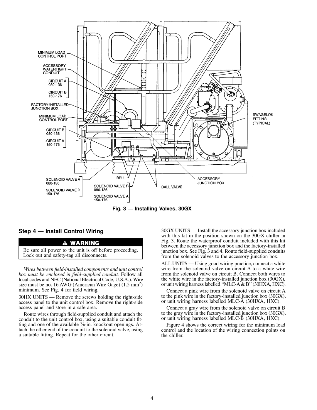
30GX UNITS Ð Install the accessory junction box included with this kit in the position shown on the 30GX chiller in Fig. 3. Route the waterproof conduit included with this kit between the accessory junction box and the factory-installed junction box. See Fig. 3 and 4. Route ®eld-supplied conduits from the solenoid valves to the accessory junction box.
ALL UNITS Ð Using good wiring practice, connect a white wire from the solenoid valve on circuit A to a white wire from the solenoid valve on circuit B. Connect both wires to the white wire in the factory-installed junction box (30GX), or unit wiring harness labelled ``MLC-A & B'' (30HXA, HXC).
Connect a pink wire from the solenoid valve on circuit A to the pink wire in the factory-installed junction box (30GX), or unit wiring harness labelled MLC-A (30HXA, HXC).
Connect a gray wire from the solenoid valve on circuit B to the gray wire in the factory-installed junction box (30GX), or unit wiring harness labelled MLC-B (30HXA, HXC).
Figure 4 shows the correct wiring for the minimum load control and the location of the wiring connection points on the chiller.