General maintenance
ATTENTION:
Before starting any servicing or maintenance operation on the unit, make sure that the power supply has been disconnected.
A current discharge could cause personal injury.
In order to obtain maximum performance from the unit special attention should be paid to the following points.
-Electrical connections:
The supply voltage should be within the limits indicated in Table II. Ensure that no faulty contacts exist in the terminal blocks, contactor boards, etc.
Make sure that all the electrical connections are properly tightened, and that all the electrical components (contactors, relays, etc) are firmly secured to the corresponding rails.
Pay special attention to the condition of the connecting cables between the control elements and the electrical box, and to that of the unit power supply cable.
They should not be twisted and there should be no slits or notches in the insulation.
Check that the starting and running consumptions are within the limits specified in Table II.
-Water connections:
Make sure there are no water leaks from the system.
Should the unit be shutdown for long periods, open the drain valve installed on the hydronic module and partially drain the pump and the water pipes as well as the drain valve on the plate-type exchanger, which must be installed on the hydraulic circuit.
This operation is essential if temperatures are expected to drop below freezing.
If the unit is not drained, the main switch should remain connected so that the defrost thermostat can operate.
Carefully clean the system water filter.
-Plate heat exchanger cleaning:
In some applications, for example when very hard water is used, there is an increased tendency for fouling.
In these cases the installation of a descaling filter is recommended.
The heat exchanger can always be cleaned by circulating a cleaning fluid.
A weak acid solution should be used (5% phosphoric acid or, if frequently cleaned 5% oxalic acid), and the cleaning fluid should be pumped through the exchanger.
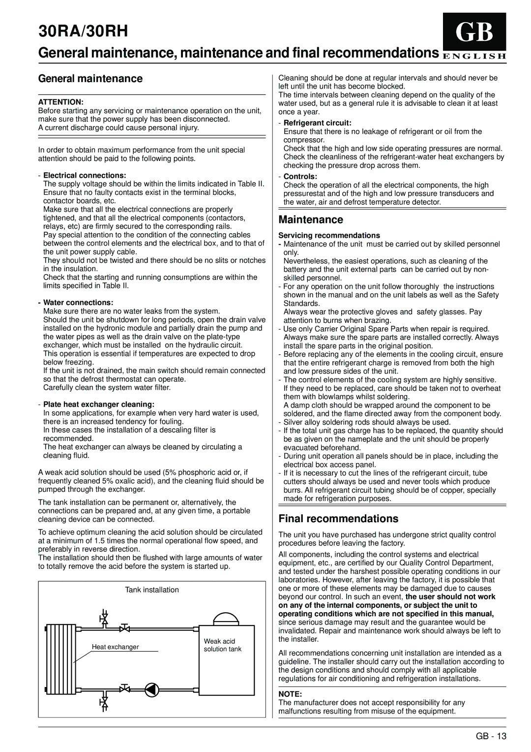
The tank installation can be permanent or, alternatively, the connections can be prepared and, at any given time, a portable cleaning device can be connected.
To achieve optimum cleaning the acid solution should be circulated at a minimum of 1.5 times the normal operational flow speed, and preferably in reverse direction.
The installation should then be flushed with large amounts of water to totally remove the acid before the system is started up.
| Tank installation | |
| Heat exchanger | Weak acid |
| solution tank |
| |
Cleaning should be done at regular intervals and should never be left until the unit has become blocked.
The time intervals between cleaning depend on the quality of the water used, but as a general rule it is advisable to clean it at least once a year.
-Refrigerant circuit:
Ensure that there is no leakage of refrigerant or oil from the compressor.
Check that the high and low side operating pressures are normal. Check the cleanliness of the refrigerant-water heat exchangers by checking the pressure drop across them.
-Controls:
Check the operation of all the electrical components, the high pressurestat and of the high and low pressure transducers and the water, air and defrost temperature detector.
Maintenance
Servicing recommendations
-Maintenance of the unit must be carried out by skilled personnel only.
Nevertheless, the easiest operations, such as cleaning of the battery and the unit external parts can be carried out by non- skilled personnel.
-For any operation on the unit follow thoroughly the instructions shown in the manual and on the unit labels as well as the Safety Standards.
Always wear the protective gloves and safety glasses. Pay attention to burns when brazing.
-Use only Carrier Original Spare Parts when repair is required. Always make sure the spare parts are installed correctly. Always install the spare parts in the original position.
-Before replacing any of the elements in the cooling circuit, ensure that the entire refrigerant charge is removed from both the high and low pressure sides of the unit.
-The control elements of the cooling system are highly sensitive. If they need to be replaced, care should be taken not to overheat them with blowlamps whilst soldering.
A damp cloth should be wrapped around the component to be soldered, and the flame directed away from the component body.
-Silver alloy soldering rods should always be used.
-If the total unit gas charge has to be replaced, the quantity should be as given on the nameplate and the unit should be properly evacuated beforehand.
-During unit operation all panels should be in place, including the electrical box access panel.
-If it is necessary to cut the lines of the refrigerant circuit, tube cutters should always be used and never tools which produce burrs. All refrigerant circuit tubing should be of copper, specially made for refrigeration purposes.
Final recommendations
The unit you have purchased has undergone strict quality control procedures before leaving the factory.
All components, including the control systems and electrical equipment, etc., are certified by our Quality Control Department, and tested under the harshest possible operating conditions in our laboratories. However, after leaving the factory, it is possible that one or more of these elements may be damaged due to causes beyond our control. In such an event, the user should not work on any of the internal components, or subject the unit to operating conditions which are not specified in this manual, since serious damage may result and the guarantee would be invalidated. Repair and maintenance work should always be left to the installer.
All recommendations concerning unit installation are intended as a guideline. The installer should carry out the installation according to the design conditions and should comply with all applicable regulations for air conditioning and refrigeration installations.
NOTE:
The manufacturer does not accept responsibility for any malfunctions resulting from misuse of the equipment.