the set points if the set point units are degrees, otherwise, they will be ignored.
The System Pilot's internal limits will not affect the display. The System Pilot reads the set points from the device and displays them as read, even if they are outside the configured System Pilot limits.
Pressing SELECT while a set point is blinking sends the new set point to the controller. Before sending the new set point to the device, the System Pilot will clamp the set point to its own internal limits and will display the clamped set point on the screen. If clamping a set point results in a value that is out- side the limits read from the device, the System Pilot will dis- play an error indication (“LIMIT”) and will not write the set point to the device.
Pressing EXIT while a set point is blinking will cause the System Pilot to revert to the original set point. Changing the set point without pressing SELECT or EXIT for 15 seconds will also cause the System Pilot to write the new set point to the controller.
The System Pilot will not write set points to the controller unless they have been changed from their original values.
Occupancy Override — To initiate an override from the Zone Controller Default Screen (if the Zone Controller’s occupancy status is UNOC), press the SELECT button for less than 3 seconds. The occupancy status will begin to blink. While the occupancy status is blinking, use the INC/DEC buttons or the MODIFY rotary knob to adjust the occupancy status. If the occupancy status is changed to OCC and then SELECT is pressed, the System Pilot sends the occupancy override to the Zone Controller.
If the occupancy status has been changed and the user does not press SELECT or EXIT within 15 seconds, the System Pilot will send the occupancy override to the controller and the occu- pancy status will stop blinking. If the occupancy status has not been changed, the System Pilot will not send occupancy status.
If the user presses EXIT while the occupancy status is blinking, the System Pilot will revert to the UNOC status. The System Pilot will not change the Zone Controller's occupancy status.
If communication to the Zone Controller fails, the System Pilot will display “COMFAIL” on the bottom line for 5 seconds.
NOTE: An occupancy override from the System Pilot will be summed into the Tenant Billing Option’s accumulation of override times. The occupancy override function is not avail- able if the System Pilot is set to security level 4.
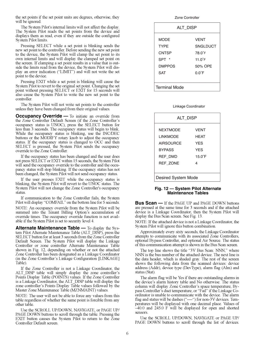
Alternate Maintenance Table — To display the Sys- tem Pilot Alternate Maintenance Table (ALT_DISP), press the SELECT button for at least 3 seconds from the Zone Controller Default Screen. The System Pilot will display the Linkage Controller or zone controller Alternate Maintenance Table shown in Fig. 12, depending on whether or not the attached Zone Controller has been designated as a Linkage Coordinator (in the Zone Controller’s Linkage Configuration [LINKAGE] Table).
If the Zone Controller is not a Linkage Coordinator, the ALT_DISP table will simply display the zone controller’s Points Display Table (POINTS) values. If the Zone Controller is a Linkage Coordinator, the ALT_DISP table will display the zone controller’s Points Display Table values followed by the Master Zone Maintenance Table (MZNMAINT) values.
NOTE: The user will not be able to force any values from this table regardless of whether the same point is forcible from any other table.
Use the SCROLL UP/DOWN, NAVIGATE, or PAGE UP/ PAGE DOWN buttons to scroll through the table. Pressing the EXIT button causes the System Pilot to return to the Zone Controller Default screen.
Fig. 12 — System Pilot Alternate
Maintenance Tables
Bus Scan — If the PAGE UP and PAGE DOWN buttons are pressed at the same time for 3 seconds and if the attached device is a Linkage Coordinator, then the System Pilot will display the Bus Scan screen. See Fig. 13.
NOTE: If the attached device is not a Linkage Coordinator, the System Pilot will ignore this button combination.
Approximately every sixty seconds, the Linkage Coordinator attempts to communicate with its associated Zone Controllers, optional Bypass Controller, and optional Air Source. The status of this communication attempt is shown in the Bus Scan screen.
The top line shows the title “3V Bus Scan: NNN,” where
NNNis the bus number of the attached device. The next line is the data header, which is shaded gray. The rest of the screen shows the following data from the scanned devices: device address (Addr), device type (DevType), alarm flag (Alm) and status (Stat).
The alarm flag will be Yes if there are outstanding alarms in the device’s alarm history table and No otherwise. The status column will display Zone Controller’s space temperature, By- pass Controller’s duct temperature, or “Fail” if the Linkage Co- ordinator is unable to communicate with the device. The alarm flag and status will be dashes (“----“) for non-3V devices. Tem-
peratures will be displayed with one decimal place. Values of –40.0 and 245.0 F will be displayed for open and shorted sensors.
Use the SCROLL UP/DOWN, NAVIGATE or PAGE UP/ PAGE DOWN buttons to scroll through the list of devices.