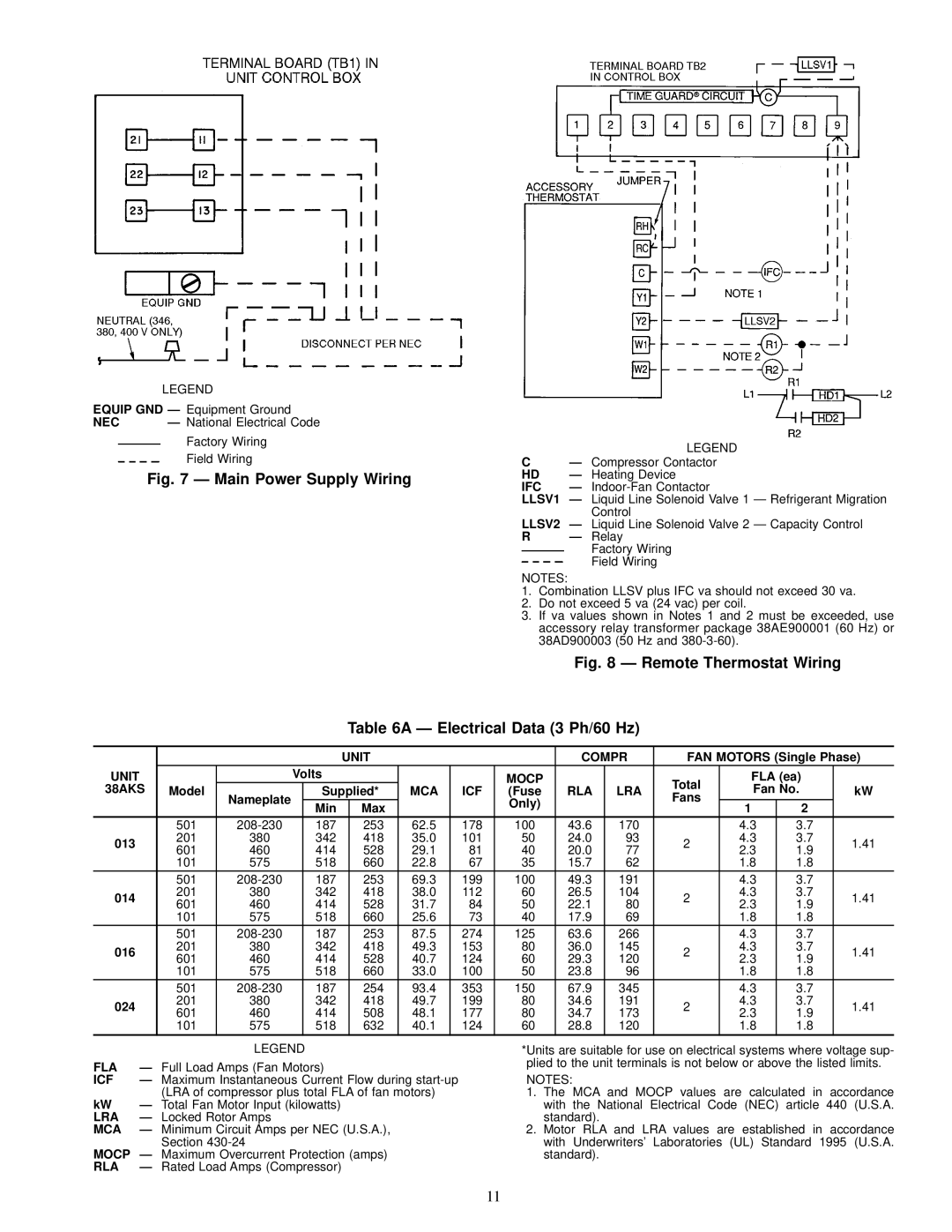
38AKS013-024 specifications
The Carrier 38AKS013-024 is a prominent series of packaged air conditioning units designed to achieve optimal performance across various applications. Engineered with advanced technologies, these units are ideal for both residential and light commercial spaces, offering reliable climate control in a compact design.The main features of the Carrier 38AKS series include high-efficiency cooling and heating capabilities. With SEER ratings that meet or exceed industry standards, these units offer reduced energy consumption, making them an environmentally friendly choice. Furthermore, the Carrier 38AKS013-024 is equipped with a scroll compressor, which enhances reliability and reduces operating noise, creating a more comfortable indoor environment.
One of the standout technologies incorporated in the Carrier 38AKS series is its advanced microprocessor control system. This technology provides precise temperature control and allows for easy integration with smart home systems. Users can conveniently manage their indoor climate through remote access, ensuring comfort at all times.
Additionally, the 38AKS series boasts durable construction materials, ensuring longevity and sustained performance even in challenging environmental conditions. The units feature a galvanized steel cabinet with a rust-resistant finish, providing protection from the elements. This design also allows for easy access to internal components during maintenance, simplifying servicing.
In terms of characteristics, the Carrier 38AKS013-024 offers a range of cooling capacities, making it suitable for various space sizes and applications. The lightweight design facilitates easy installation, while the low noise levels ensure minimal disruption in residential settings. These units also come with environmentally friendly refrigerants, aligning with modern sustainability goals.
Carrier's commitment to quality and performance is evident in the 38AKS series. With their combination of innovative technology, energy efficiency, and robust construction, the Carrier 38AKS013-024 units represent an excellent choice for those seeking a reliable and efficient air conditioning solution. Whether for home or light commercial use, these units promise consistent comfort and satisfaction.

