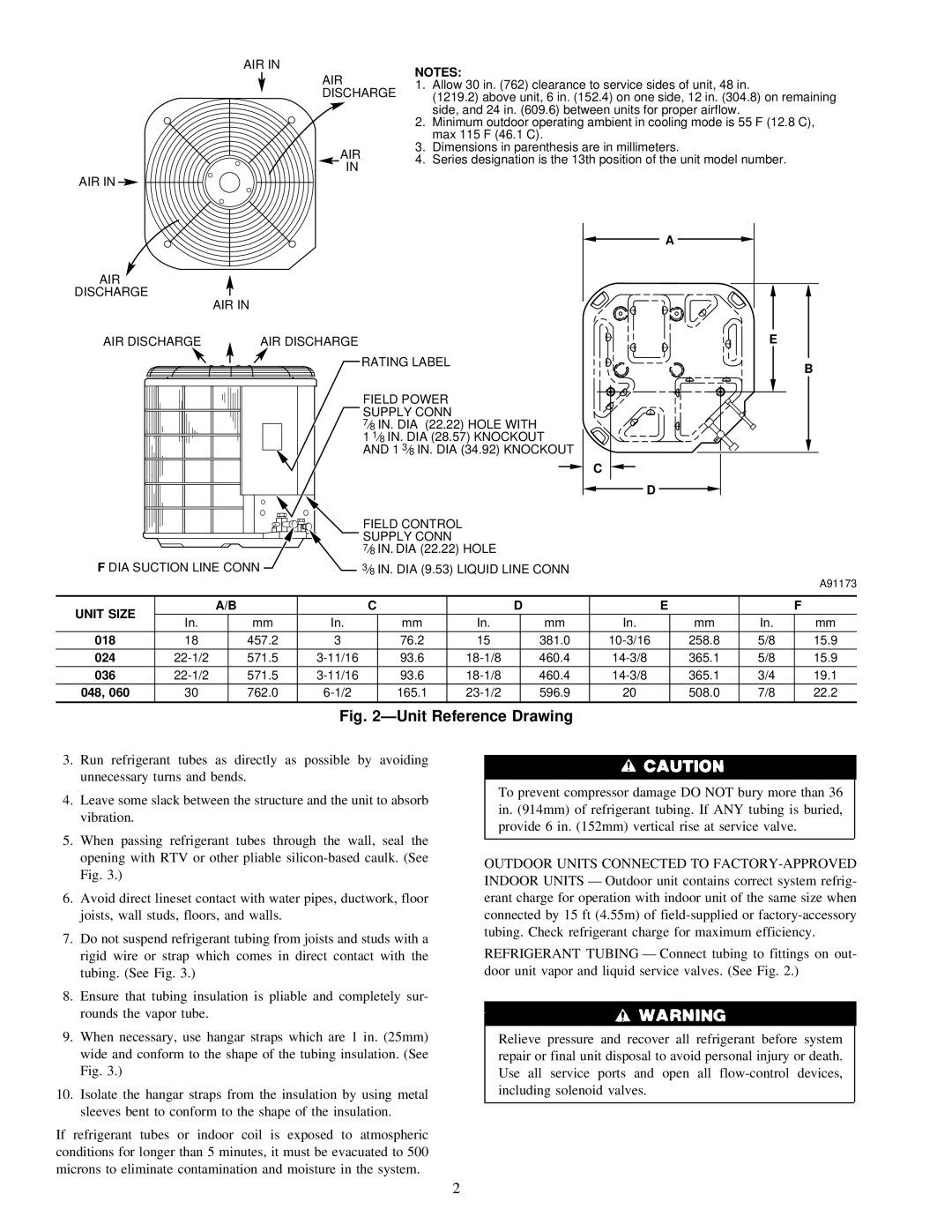
38CKB specifications
The Carrier 38CKB is a cutting-edge air conditioning unit designed to offer optimal cooling and energy efficiency for both residential and commercial applications. Renowned for its robust construction and advanced technology, the 38CKB stands out as an excellent choice for customers seeking reliability and performance.One of the standout features of the Carrier 38CKB is its high Energy Efficiency Ratio (EER), which translates to lower operating costs and reduced energy consumption. This unit is designed with the environment in mind, helping users minimize their carbon footprint while enjoying the comfort of a cool indoor environment. The system utilizes a high-efficiency scroll compressor that operates quietly and smoothly, further enhancing the user experience.
The 38CKB incorporates a variety of innovative technologies that contribute to its superior performance. Among these is the variable-speed fan motor, which can adjust its operation based on the cooling needs of the space. This means that the system not only delivers effective cooling but also does so with maximum efficiency, reducing wear and tear and extending the lifespan of the unit.
In terms of design, the 38CKB features a compact and aesthetically pleasing exterior, making it suitable for installation in diverse settings. The unit is equipped with a durable cabinet that ensures long-term reliability against environmental challenges, including weather and outdoor conditions. Additionally, the unit can be easily serviced, as it provides convenient access to critical components for maintenance and repairs.
Safety and control features are also prominent in the 38CKB. It is equipped with advanced diagnostic capabilities that alert users to any potential issues, allowing for proactive maintenance and minimizing downtime. Moreover, Carrier offers a range of smart thermostats compatible with this unit, enabling users to manage their cooling systems remotely, providing convenience and customizable comfort.
Overall, the Carrier 38CKB emerges as a versatile air conditioning solution, catering to the needs of various users with its blend of efficiency, innovative technology, and user-friendly features. Whether for home use or commercial spaces, the 38CKB is engineered to deliver reliable performance while emphasizing energy savings and environmental responsibility.

