DUAL CAPACITY |
|
|
|
|
|
|
|
|
|
|
|
|
|
| ||
CONNECTION DIAGRAM L1 |
|
|
| BLK |
|
|
|
|
| BRN |
| |||||
208 / 230 - 1 - 60 |
| L2 |
|
| YEL |
|
|
| BLK |
|
|
|
| |||
|
|
|
|
|
|
|
|
| RED |
| ||||||
POWER SUPPLY |
|
|
|
|
|
|
|
| BLU |
|
|
|
| |||
|
|
|
|
|
| CH |
|
| 11 |
|
| |||||
|
|
|
|
|
|
|
|
|
|
|
|
|
| |||
|
|
|
|
|
|
|
| 23 | 11 |
|
| 23 |
|
| ||
|
|
|
|
|
|
|
|
|
|
|
|
|
| |||
|
|
|
|
|
|
|
|
|
|
| C L |
|
|
|
|
|
|
| EQUIP GND |
|
|
|
| 23 | 21 |
|
| 23 | 21 |
|
| ||
|
|
|
|
|
|
|
|
|
|
|
| |||||
|
|
|
|
|
|
|
|
| YEL |
|
|
|
|
| NOTE #10 | |
|
|
|
|
|
|
|
|
| BRN |
|
|
|
|
| ||
|
|
|
|
|
|
|
|
|
|
| BLK | BLU | R | COMP | ||
|
|
|
|
|
| RED |
|
| BLU |
|
| C | ||||
|
|
|
|
|
|
|
|
|
|
|
|
| ||||
|
|
|
|
|
| BLU |
|
|
|
| BLU |
|
|
|
| |
|
|
|
|
|
|
|
|
|
|
|
|
|
|
| ||
PL1 | 1 | 2 | 3 | 4 | 5 | 1 | 2 |
| BRN |
| BRN |
|
| S |
| YEL |
PL2 |
|
|
|
|
|
|
|
| ||||||||
| HP/AC | C | EXV | RVS | C | HI | LO |
|
|
| BRN |
|
|
|
| |
|
|
|
|
|
|
| LPS | 1 |
| LPS |
|
|
|
|
| |
|
|
|
|
|
|
|
| START |
|
|
|
| ||||
FORCED |
|
|
|
|
| PL3 | 2 | YEL/PNK |
| CAP |
|
|
|
| ||
|
|
|
|
|
|
|
|
|
| C |
|
| ||||
|
|
|
|
|
| 3 | YEL/PNK |
|
| COMP |
|
|
| |||
DEFROST |
|
|
|
|
|
|
|
|
|
|
|
| ||||
|
|
|
|
| HPS |
|
| HPS | BRN | CAP |
|
|
|
| ||
|
|
|
|
|
|
|
| BLU/PNK |
|
| H |
|
| |||
|
|
|
|
|
|
| 1 |
|
|
|
|
|
| |||
DEFROST |
|
|
| PWM 2 | BLU PL4 | 2 | BLU/PNK |
|
| YEL |
|
|
|
| ||
|
|
| PWM 1 |
|
|
|
| OAT | 5 | 1 |
|
|
|
| ||
TIME (MIN) |
|
|
|
| OAT | 1 |
| BLU |
|
|
| |||||
|
|
|
|
| YEL |
| BLK |
|
| 2 |
|
|
|
| ||
|
|
|
|
|
|
| PL5 | 2 | BLK |
|
|
| BLU |
|
| |
|
|
|
|
|
|
| OCT |
|
|
|
|
| ||||
|
|
|
|
|
|
| START RELAY |
|
| BRN |
| |||||
|
|
|
|
|
|
|
|
|
|
|
|
| ||||
O |
|
| COMM STATUS |
| OCT | 4 | BRN |
|
|
|
|
|
|
| ||
|
|
|
|
|
| 5 | BRN |
|
|
|
|
|
|
| ||
Y 2 |
|
|
|
|
|
| VC |
|
|
|
|
|
|
| YEL BLU | GRN/YEL |
Y1 |
|
|
|
|
|
|
|
|
|
|
|
|
| |||
|
|
|
|
|
| BRN |
|
|
|
|
|
|
| |||
W1 |
|
|
| A B | C D |
| VH | BLU |
|
|
|
|
|
|
| BRN |
|
|
|
| ODF |
|
|
|
|
|
|
| |||||
C |
|
|
|
|
|
| BLK |
|
|
|
|
| OFM |
| ||
R |
|
|
|
|
|
| L 2 |
|
|
|
|
|
|
| ||
|
|
|
|
|
| YEL |
|
|
|
|
|
|
|
| ||
|
|
|
|
|
| CCH |
|
|
|
|
|
|
| RED | ||
|
|
|
|
|
|
|
| RED |
|
| CCH |
|
|
|
|
|
|
|
|
|
|
|
|
|
|
|
|
|
|
|
|
| |
TO INDOOR UNIT |
|
|
|
|
|
|
|
|
|
|
|
|
| |||
|
|
|
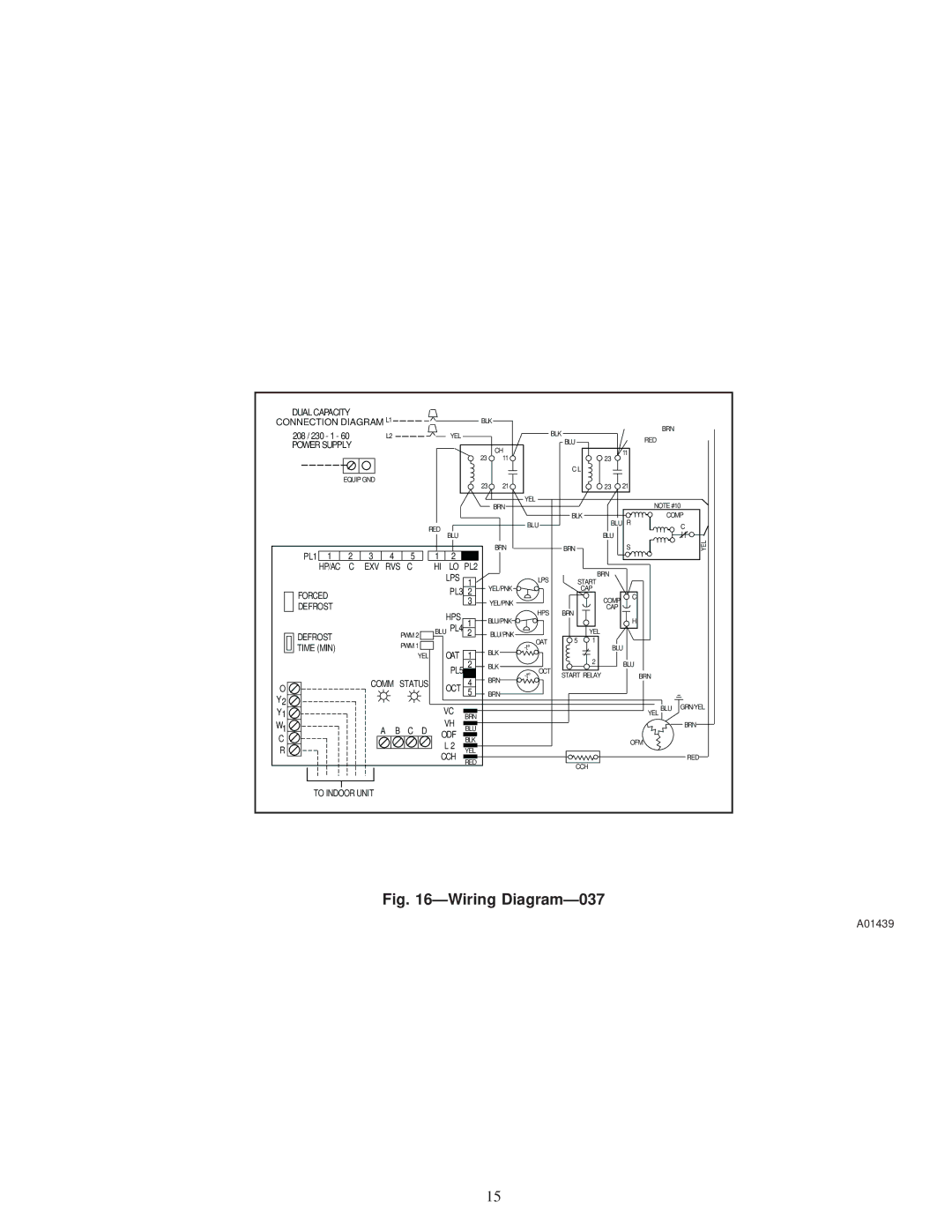
| Fig. |
|
|
|
| ||||||||
A01439
15