PROGRAMMABLE | FK4C, FV4A |
|
|
| |||||||||||||
THERMOSTAT |
| ||||||||||||||||
MODEL 2S |
|
|
|
| OR 40FK | AIR CONDITIONER | |||||||||||
|
|
|
|
|
|
|
| FAN COIL |
|
|
| ||||||
|
|
|
|
|
|
|
|
|
|
|
|
|
|
|
|
|
|
|
|
|
|
|
|
|
|
|
|
| DH |
|
|
| J1 |
|
|
24 VAC HOT |
| R |
|
|
| R |
| JUMPER | R |
| |||||||
|
|
|
|
|
|
| |||||||||||
FAN |
| G |
|
|
| G |
|
|
|
| |||||||
|
|
|
|
|
|
|
|
| Y1 |
|
| Y1 |
| ||||
COOL STAGE 1 |
| Y1/W2 |
|
|
|
|
|
|
| ||||||||
|
|
|
|
|
|
|
|
|
|
| |||||||
COOL STAGE 2 |
| Y/Y2 |
|
|
| Y/Y2 |
|
|
| Y2 |
| ||||||
HEAT STAGE 1 |
|
|
|
|
|
|
| W1 |
| REMOVE |
|
| |||||
| W/W1 |
|
|
|
|
| J2 JUMPER |
|
| ||||||||
HEAT STAGE 2 |
|
|
|
|
|
|
|
|
|
|
| FOR HEAT |
|
| |||
| O/W2 |
|
|
|
|
| W2 |
| STAGING |
|
| ||||||
24 VAC COMM |
| C |
|
|
| C |
|
| C |
| |||||||
N/A |
| B |
|
|
| O |
|
|
|
| |||||||
|
|
|
|
|
|
|
|
|
|
|
|
|
|
|
|
| |
OUTDOOR |
|
|
| S1 |
|
|
|
|
|
|
|
|
|
| |||
|
|
|
|
|
|
|
|
|
|
|
|
| |||||
|
|
|
|
|
|
|
|
|
|
|
|
|
|
| |||
SENSOR |
|
|
|
|
|
|
|
|
|
|
|
|
|
|
|
|
|
CONNECTION |
|
|
| S2 |
|
|
|
|
|
|
|
|
|
| |||
|
|
|
|
|
|
|
|
|
|
|
|
| |||||
|
|
|
|
|
|
|
|
|
|
|
|
|
|
|
|
|
|
|
|
|
|
|
|
|
|
|
|
|
|
|
|
|
|
|
|
THERMIDISTAT |
| FK4C, FV4A |
| |||||||
CONTROL |
| OR 40FK | AIR CONDITIONER | |||||||
MODEL RH |
| FAN COIL |
|
|
| |||||
|
|
|
|
|
|
|
|
|
|
|
HEAT STAGE 2 O/W2 |
|
|
|
|
|
|
|
|
| |
|
|
| W2 |
|
|
| ||||
|
|
| REMOVE J2 JUMPER |
HEAT STAGE 1 | W/W1 | W1 | FOR HEAT STAGING |
| |||
COOL STAGE 1 Y1/W2 | Y1 | Y1 | |
COOL STAGE 2 | Y/Y2 | Y/Y2 | Y2 |
FAN | G | G |
|
24 VAC HOT | R | R | R |
|
| ||
|
| O | REMOVE |
|
| J1 JUMPER | |
|
|
| |
DEHUMIDIFY | DHUM | DH |
|
24 VAC COMM | C | C | C |
HUMIDIFY | HUM | HUMIDIFIER | |
|
| (24 VAC) |
|
N/A |
| B |
|
| ||
|
|
|
|
|
| OUTDOOR |
OUTDOOR |
| S1 |
| SENSOR | ||
SENSOR |
|
| S2 |
|
| |
CONNECTION |
|
|
| |||
|
|
|
|
|
|
|
See notes 1, 2, 3, 5, and 7 |
| ||
| A01493 |
| |
PROGRAMMABLE | |||
CONDENSING | |||
THERMOSTAT | |||
FURNACE | AIR CONDITIONER | ||
MODEL 2S | |||
|
| ||
See notes 1, 2, 3, 6, 7, 8, and 9 A01494
HEAT STAGE 2 | O/W2 |
| |
|
|
|
|
COOL STAGE 1 | Y1/W2 |
| |
|
|
|
|
HEAT STAGE 1 | W/W1 |
| |
|
|
| |
COOL STAGE 2 | Y/Y2 |
| |
|
|
|
|
FAN | G |
| |
|
|
|
|
24 VAC HOT | R |
|
|
24 VAC COMM |
| C | ||
|
|
|
|
|
N/A |
| B | ||
|
|
|
|
|
OUTDOOR |
| S1 | ||
|
|
| ||
SENSOR |
|
|
|
|
CONNECTION |
| S2 | ||
|
|
|
|
|
W2
![]() Y1
Y1
W/W1
Y/Y2 ![]()
![]() Y2
Y2
G
R ![]()
![]() R
R
DEHUM
DE JUMPER
CC
HUM ![]()
![]()
See notes 1, 2, 3, and 5
A01507
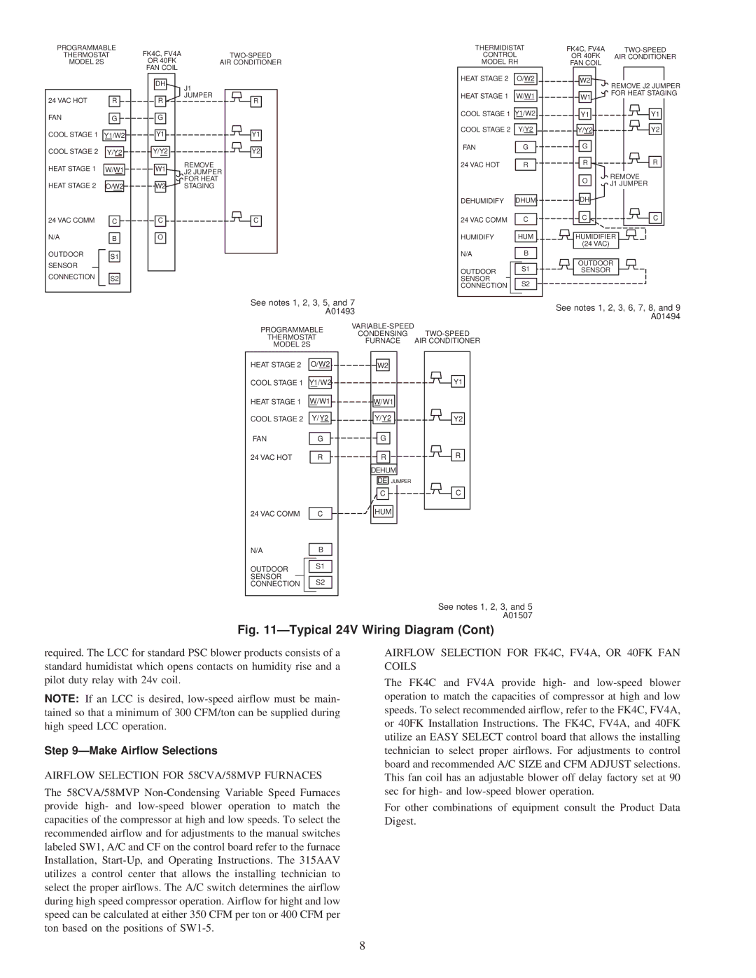
Fig. 11—Typical 24V Wiring Diagram (Cont)
required. The LCC for standard PSC blower products consists of a standard humidistat which opens contacts on humidity rise and a pilot duty relay with 24v coil.
NOTE: If an LCC is desired,
Step 9—Make Airflow Selections
AIRFLOW SELECTION FOR 58CVA/58MVP FURNACES
The 58CVA/58MVP
AIRFLOW SELECTION FOR FK4C, FV4A, OR 40FK FAN COILS
The FK4C and FV4A provide high- and
For other combinations of equipment consult the Product Data Digest.
8