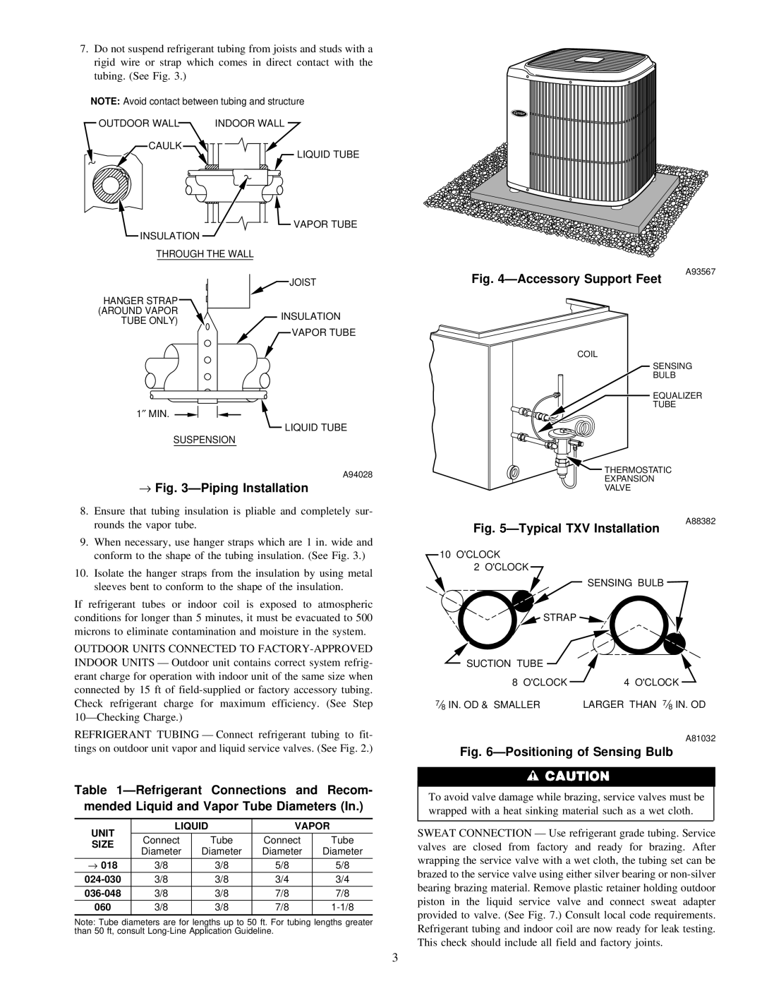
7.Do not suspend refrigerant tubing from joists and studs with a rigid wire or strap which comes in direct contact with the tubing. (See Fig. 3.)
NOTE: Avoid contact between tubing and structure
OUTDOOR WALL INDOOR WALL
CAULK
![]() LIQUID TUBE
LIQUID TUBE
VAPOR TUBE
INSULATION
THROUGH THE WALL
| JOIST | |
HANGER STRAP |
| |
(AROUND VAPOR | INSULATION | |
TUBE ONLY) | ||
| ||
| VAPOR TUBE |
Fig. 4ÐAccessory Support Feet
COIL
A93567
1″ MIN.
LIQUID TUBE
SUSPENSION
A94028
→ Fig. 3ÐPiping Installation |
8. Ensure that tubing insulation is pliable and completely sur- |
SENSING
BULB
EQUALIZER
TUBE
![]() THERMOSTATIC EXPANSION VALVE
THERMOSTATIC EXPANSION VALVE
| rounds the vapor tube. |
9. | When necessary, use hanger straps which are 1 in. wide and |
| conform to the shape of the tubing insulation. (See Fig. 3.) |
10. | Isolate the hanger straps from the insulation by using metal |
Fig. 5ÐTypical TXV Installation
10 O'CLOCK
2 O'CLOCK
A88382
sleeves bent to conform to the shape of the insulation. |
If refrigerant tubes or indoor coil is exposed to atmospheric conditions for longer than 5 minutes, it must be evacuated to 500 microns to eliminate contamination and moisture in the system.
OUTDOOR UNITS CONNECTED TO
REFRIGERANT TUBING Ð Connect refrigerant tubing to fit- tings on outdoor unit vapor and liquid service valves. (See Fig. 2.)
Table 1ÐRefrigerant Connections and Recom- mended Liquid and Vapor Tube Diameters (In.)
UNIT | LIQUID | VAPOR | |||
Connect | Tube | Connect | Tube | ||
SIZE | |||||
Diameter | Diameter | Diameter | Diameter | ||
| |||||
→ 018 | 3/8 | 3/8 | 5/8 | 5/8 | |
3/8 | 3/8 | 3/4 | 3/4 | ||
3/8 | 3/8 | 7/8 | 7/8 | ||
060 | 3/8 | 3/8 | 7/8 | ||
Note: Tube diameters are for lengths up to 50 ft. For tubing lengths greater than 50 ft, consult
SENSING BULB |
STRAP |
SUCTION TUBE |
8 O'CLOCK | 4 O'CLOCK |
7⁄8 IN. OD & SMALLER | LARGER THAN 7⁄8 IN. OD |
| A81032 |
Fig. 6ÐPositioning of Sensing Bulb
To avoid valve damage while brazing, service valves must be wrapped with a heat sinking material such as a wet cloth.
SWEAT CONNECTION Ð Use refrigerant grade tubing. Service valves are closed from factory and ready for brazing. After wrapping the service valve with a wet cloth, the tubing set can be brazed to the service valve using either silver bearing or
3