THERMOSTAT
MODEL HP
24 VAC HOT | R |
|
|
24 VAC COM |
|
C |
FK4B | HEAT |
FAN COIL | PUMP |
R | R |
C | C |
|
| |
FA, FB, FC, |
| |
THERMOSTAT | FD, FF | HEAT |
MODEL HP | FAN COIL | PUMP |
HEAT STAGE 2 | W | ||
COOL/HEAT |
| ||
| |||
Y | |||
STAGE 1 | |||
| |||
| |||
|
|
| |
INDOOR FAN |
| G | |
| |||
| |||
|
|
| |
RVS COOLING |
|
| |
| O | ||
EMERGENCY |
|
| |
| E | ||
HEAT |
|
| |
| |||
|
|
| |
W2 | W2 |
Y/Y2 | Y |
G |
|
W3 |
|
O | O |
Y1 |
|
E |
|
L |
|
24 VAC HOT
24 VAC COM
HEAT STAGE 2
COOL/HEAT STAGE 1
INDOOR FAN
RVS COOLING
EMERGENCY HEAT
R | R | R |
C | C | C |
W | W2 | W2 |
Y |
| Y |
G | G |
|
O |
| O |
E |
|
|
A95279 | A95280 | |
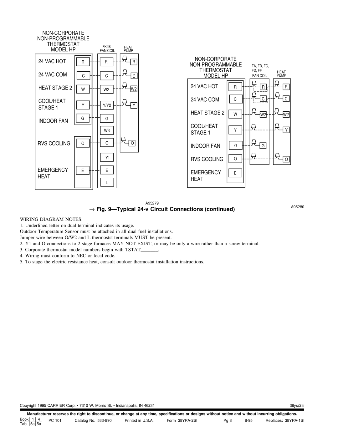
→ Fig. 9ÐTypical | ||
|
WIRING DIAGRAM NOTES:
1. Underlined letter on dual terminal indicates its usage.
Outdoor Temperature Sensor must be attached in all dual fuel installations. Jumper wire between O/W2 and L thermostst terminals MUST be present.
2.Y1 and O connections to
3.Corporate thermostat model numbers begin with TSTAT_______.
4.Wiring must conform to NEC or local code.
5.To stage the electric resistance heat, consult outdoor thermostat installation instructions.
Copyright 1995 CARRIER Corp. · 7310 W. Morris St. · Indianapolis, IN 46231 | 38yra2si |
|
|
Manufacturer reserves the right to discontinue, or change at any time, specifications or designs without notice and without incurring obligations.
Book | 1 | 4 | PC 101 | Catalog No. | Printed in U.S.A. | Form | Pg 8 | Replaces: | ||
| Tab | 5a | 5a |
|
|
|
|
|
|
|
