42 GW
Motorized valve and control
E N G L I S H
•If these connections are not made as described the drain pan condensate may overflow.
•Valves should only open when the fan motor is working, i.e. when one of TB1 terminals 1 or 2 or 3 is supplied from TB1 terminal 4.
•The optional electric heater (mod. 42GWE) which can only be factory installed, must only be energized when the fan is working.
•The optional electric heater which must be factory installed on model 42GWE, works only if TB1 terminals
•The water discharge pump should work every time the cold water valve is opened, supplying TB1 terminal 7 and 8 from TB1 terminal 4.
•When the system is filled with water, verify all couplings for tightness.
•The manufacturer does not accept responsibility for the tightness of the field - installed valve assembly and this is not tested in the factory. He declines any responsibility for non functioning of these assemblies and for damage due to dripping.
Electrical connections
We recommend to remove the main board from the electric panelboard for better access to electric connections.
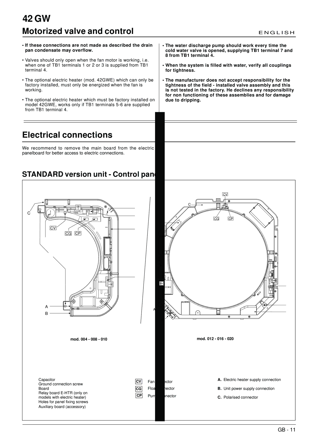
STANDARD version unit - Control panel
CV
C ![]()
C
CG | CP |
CV
CG CP
A
B
A
B
mod. 004 - 008 - 010 | mod. 012 - 016 - 020 |
Capacitor |
|
|
| A. Electric heater supply connection |
| CV | Fan connector | ||
Ground connection screw |
|
| ||
|
| Float connector | B. Unit power supply connection | |
Board |
| CG | ||
Relay board |
|
|
|
|
| CP | Pump connector | C. Polarised connector | |
models with electric heater) |
| |||
|
|
| ||
Holes for panel fixing screws |
|
|
|
|
Auxiliary board (accessory) |
|
|
|
|
GB - 11