42 GW
Fresh air renewal and conditioned air supply to an adjacent room
49 105 120
C
B
A Ø
216
A Ø
|
|
|
| Duct connection flange | |
|
|
|
| Clip | |
|
|
|
| 6 mm neoprene gasket | |
Model |
|
|
| ||
| Insulated flexible duct | ||||
Ø A | mm | 150 | 150 | Fresh air intake | |
|
|
|
| Conditioned air supply to an | |
B | mm | 120 | 120 | ||
adjacent room | |||||
Ø C | mm | 70 | 100 | ||
Polystyrene partition | |||||
|
|
|
| Baffle | |
|
|
|
| ||
|
|
|
| Frame |
Air intake grille
Wall
Undercut door
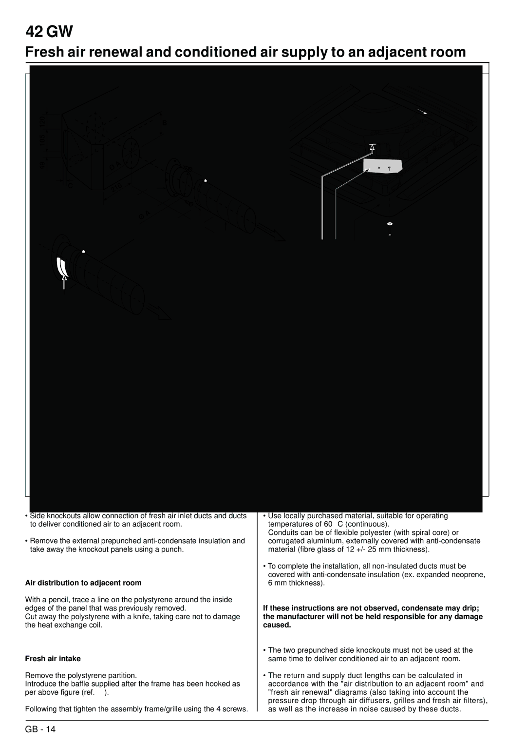
•Side knockouts allow connection of fresh air inlet ducts and ducts to deliver conditioned air to an adjacent room.
•Remove the external prepunched
Air distribution to adjacent room
With a pencil, trace a line on the polystyrene around the inside edges of the panel that was previously removed.
Cut away the polystyrene with a knife, taking care not to damage the heat exchange coil.
Fresh air intake
Remove the polystyrene partition.
Introduce the baffle supplied after the frame has been hooked as per above figure (ref. ).
Following that tighten the assembly frame/grille using the 4 screws.
•Use locally purchased material, suitable for operating temperatures of 60 ° C (continuous).
Conduits can be of flexible polyester (with spiral core) or corrugated aluminium, externally covered with
•To complete the installation, all
If these instructions are not observed, condensate may drip; the manufacturer will not be held responsible for any damage caused.
•The two prepunched side knockouts must not be used at the same time to deliver conditioned air to an adjacent room.
•The return and supply duct lengths can be calculated in accordance with the "air distribution to an adjacent room" and "fresh air renewal" diagrams (also taking into account the pressure drop through air diffusers, grilles and fresh air filters), as well as the increase in noise caused by these ducts.
GB - 14
