42 GW
Electrical connections
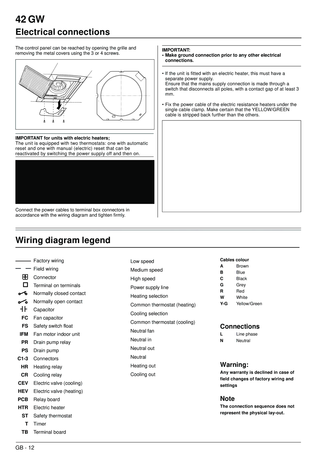
The control panel can be reached by opening the grille and removing the metal covers using the 3 or 4 screws.
IMPORTANT for units with electric heaters;
The unit is equipped with two thermostats: one with automatic reset and one with manual (electric) reset that can be reactivated by switching the power supply off and then on.
IMPORTANT:
•Make ground connection prior to any other electrical connections.
•If the unit is fitted with an electric heater, this must have a separate power supply.
Ensure that the mains supply connection is made through a switch that disconnects all poles, with a contact gap of at least 3 mm.
•Fix the power cable of the electric resistance heaters under the single cable clamp. Make certain that the YELLOW/GREEN cable is stripped back further than the others.
Connect the power cables to terminal box connectors in accordance with the wiring diagram and tighten firmly.
Wiring diagram legend
|
|
|
|
|
|
| Factory wiring | Low speed |
|
|
|
|
|
| |||
|
|
|
|
|
|
| Field wiring | Medium speed |
|
|
|
|
|
|
| ||
|
|
|
|
|
|
| Connector | High speed |
|
|
|
|
|
|
| Terminal on terminals | Power supply line |
|
|
|
|
|
|
|
| |
|
|
|
|
|
|
| Normally closed contact | Heating selection |
|
|
|
|
|
|
| Normally open contact | |
|
|
|
|
|
|
| Common thermostat (heating) | |
|
|
|
|
|
|
| Capacitor | |
|
|
|
|
|
|
| Cooling selection | |
|
| FC |
| Fan capacitor | ||||
|
|
| Common thermostat (cooling) | |||||
|
| FS |
| Safety switch float | ||||
|
|
| Neutral fan | |||||
IFM |
| Fan motor indoor unit | ||||||
| Neutral in | |||||||
|
| PR |
| Drain pump relay | ||||
|
|
|
| |||||
|
| PS |
| Drain pump | Neutral out | |||
|
|
|
| |||||
| Connectors | Neutral | ||||||
|
| |||||||
|
| HR |
| Heating relay | Heating out | |||
|
| CR |
| Cooling relay | Cooling out | |||
CEV |
| Electric valve (cooling) |
| |||||
HEV |
| Electric valve (heating) |
| |||||
PCB |
| Relay board |
| |||||
HTR |
| Electric heater |
| |||||
|
| ST |
| Safety thermostat |
| |||
TTimer
TB Terminal board
Cables colour
ABrown
BBlue
CBlack
GGrey
RRed
WWhite
Connections
LLine phase
NNeutral
Warning:
Any warranty is declined in case of field changes of factory wiring and settings
Note
The connection sequence does not represent the physical
GB - 12