Carrier 48HC installation instructions Typical 3/4-in NPT Field Supplied Piping Parts

Models: 48HC

1 52
Download 52 pages 22.22 Kb
Page 17
Image 17

Table 2 – Typical 3/4-in NPT Field Supplied Piping Parts

Item

Qty

CPN

Description


1

1

CA15RA201

90 Deg Street Elbow


2

1

CA01CA226

5 Inch Long Nipple

5

4

3

2

6


1


3

1

CA85RA201

Ground--- Joint Union


4

1

CA01CA218

3 Inch Long Nipple


5

1

CA05RA201

90 Deg Elbow


6

1

CA01CA250

12 Inch Long Nipple


7

1

CA05RA201

90 Deg Elbow


8

1

CA01CA218

3 Inch Long Nipple


9

1

CA20RA201

TEE


10

1

CA01CN222

4 Inch Long Nipple (Sediment Trap)


11

1

CA38RA201

Cap


12

1

CA01CA220

3 1/2 Inch Long Nipple

13

1

GB30

NIBCOR Ball Valve

7

8

9

10

11

12

13

15

14

14

1

CA01CA238

8 Inch Long Nipple


15

1

CA05RA201

90 Deg Elbow

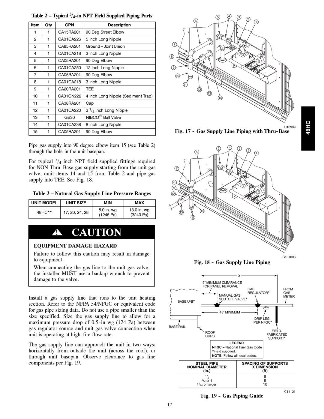
Pipe gas supply into 90 degree elbow item 15 (see Table 2) through the hole in the unit basepan.

For typical 3/4 inch NPT field supplied fittings required for NON Thru-Base gas supply starting from the unit gas valve, omit items 14 and 15 from Table 2 and pipe gas supply into TEE. See Fig. 18.

Table 3 – Natural Gas Supply Line Pressure Ranges

UNIT MODEL

UNIT SIZE

MIN

MAX


48HC**

17, 20, 24, 28

5.0 in. wg

13.0 in. wg


(1246 Pa)

(3240 Pa)


!

CAUTION


EQUIPMENT DAMAGE HAZARD

Failure to follow this caution may result in damage to equipment.

When connecting the gas line to the unit gas valve, the installer MUST use a backup wrench to prevent damage to the valve.

Install a gas supply line that runs to the unit heating section. Refer to the NFPA 54/NFGC or equivalent code for gas pipe sizing data. Do not use a pipe smaller than the size specified. Size the gas supply line to allow for a maximum pressure drop of 0.5-in wg (124 Pa) between gas regulator source and unit gas valve connection when unit is operating at high-fire flow rate.

The gas supply line can approach the unit in two ways: horizontally from outside the unit (across the roof), or through unit basepan. Observe clearance to gas line components per Fig. 19.


C10999

48HC

Fig. 17 - Gas Supply Line Piping with Thru-Base

5

4

3

2


6


1


7

8 9 12

1310

11


C101006

Fig. 18 - Gas Supply Line Piping


X


9” MINIMUM CLEARANCE


FOR PANEL REMOVAL


GAS

FROM


REGULATOR*

GAS


MANUAL GAS

METER


SHUTOFF VALVE*


BASE UNIT


48” MINIMUM

DRIP LEG

PER NFGC*

BASE RAIL

ROOF


FIELD-


FABRICATED

CURB


SUPPORT*


LEGEND


NFGC – National Fuel Gas Code


*Field supplied.


NOTE: Follow all local codes.


STEEL PIPE


SPACING OF SUPPORTS

NOMINAL DIAMETER


X DIMENSION

(in.)


(ft)

1/2


6

3/4 or 1


8

11/4 or larger


10

Fig. 19 - Gas Piping Guide

C11121

17

Page 17
Image 17
Carrier 48HC Typical 3/4-in NPT Field Supplied Piping Parts, Natural Gas Supply Line Pressure Ranges

48HC specifications

The Carrier 48HC is a highly efficient rooftop HVAC unit designed for commercial applications that prioritize both performance and energy savings. This unit embodies Carrier's commitment to innovation by integrating advanced technologies and features that address the modern demands of building climate control.

One of the standout features of the Carrier 48HC is its exceptional energy efficiency. Employing the latest in variable-speed compressor technology, the unit adjusts its output based on the specific cooling needs of the space, which not only enhances comfort levels but also significantly reduces energy consumption. This feature is crucial for businesses looking to lower their operational costs while minimizing their environmental impact.

The Carrier 48HC is also equipped with a comprehensive range of control options. Through its intelligent control systems, users can utilize features such as demand ventilation, which optimizes indoor air quality while maintaining energy efficiency. The integration with building management systems (BMS) further enhances operational effectiveness, allowing real-time monitoring and adjustments from a centralized point.

Additionally, the 48HC is designed with durability in mind. Its robust construction resists harsh weather conditions and ensures long-lasting performance. The unit features advanced corrosion-resistant materials and coatings, which prolong its lifespan and reduce maintenance needs. This durability makes the 48HC a reliable choice for varying environments, whether it’s an industrial setting or a more delicate commercial space.

The unit’s compact design also deserves mention, as it facilitates easier installation on rooftops without taking up excessive space. The modular design allows for customization, enabling businesses to tailor their systems to fit specific heating and cooling requirements.

In terms of comfort, the Carrier 48HC employs efficient air distribution technology that ensures even airflow throughout the space. This greatly enhances occupant comfort by eliminating hot or cold spots, promoting a consistent indoor climate.

Finally, the 48HC complies with stringent environmental regulations and standards. With options for environmentally-friendly refrigerants, it supports businesses in their sustainability efforts while operating effectively under current regulations.

In summary, the Carrier 48HC stands out in the crowded HVAC market due to its advanced technology, energy efficiency, durability, and adaptability for commercial applications, making it a top choice for those looking to invest in a reliable and effective climate control solution.