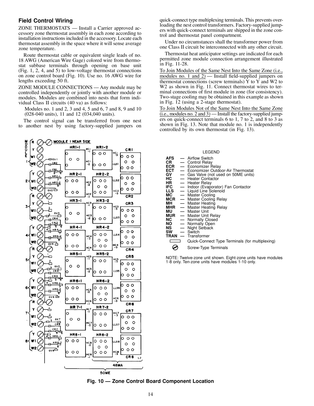
48MA/50ME016-040 specifications
The Carrier 48MA/50ME016-040 series represents a significant advancement in the field of commercial HVAC systems, designed to provide reliable, efficient, and effective climate control solutions for various applications. These units are widely recognized for their durability and performance, making them a top choice for building owners and managers seeking optimal comfort and energy efficiency.One of the main features of the Carrier 48MA/50ME series is its advanced scroll compressor technology. The scroll compressors are known for their reliability and efficiency, which leads to reduced energy consumption and lower operating costs. This high-efficiency design not only contributes to significant energy savings but also minimizes noise levels, enhancing the overall comfort of the environment.
The units are equipped with a unique microprocessor-based control system that offers precise temperature control and flexibility. This technology allows for easy integration with building management systems, enabling users to monitor and control their HVAC systems remotely, thereby optimizing performance and energy use. The programmable thermostats help to tailor the operation of the units to meet the specific needs of the users, ensuring maximum comfort at all times.
In addition to its robust performance features, the Carrier 48MA/50ME series also boasts a comprehensive line of options for customization. These options include various cooling capacities ranging from 16 to 40 tons, allowing the equipment to cater to different building sizes and requirements. The series is also designed with a compact footprint, making it suitable for rooftop installations where space is at a premium.
Another important characteristic of the series is its environmentally friendly refrigerant options. Carrier prioritizes the use of refrigerants with low global warming potential, contributing to a more sustainable approach to HVAC solutions. This commitment to environmental responsibility not only complies with regulations but also meets the increasing demand for greener technologies.
Furthermore, the robust construction of the Carrier 48MA/50ME series ensures long-lasting performance in even the harshest conditions. The units are designed to withstand various environmental factors, making them ideal for both commercial and industrial applications. Overall, the Carrier 48MA/50ME016-040 series stands out as a reliable choice for efficient and effective heating and cooling solutions, equipped with innovative technologies that prioritize performance, sustainability, and user comfort.

