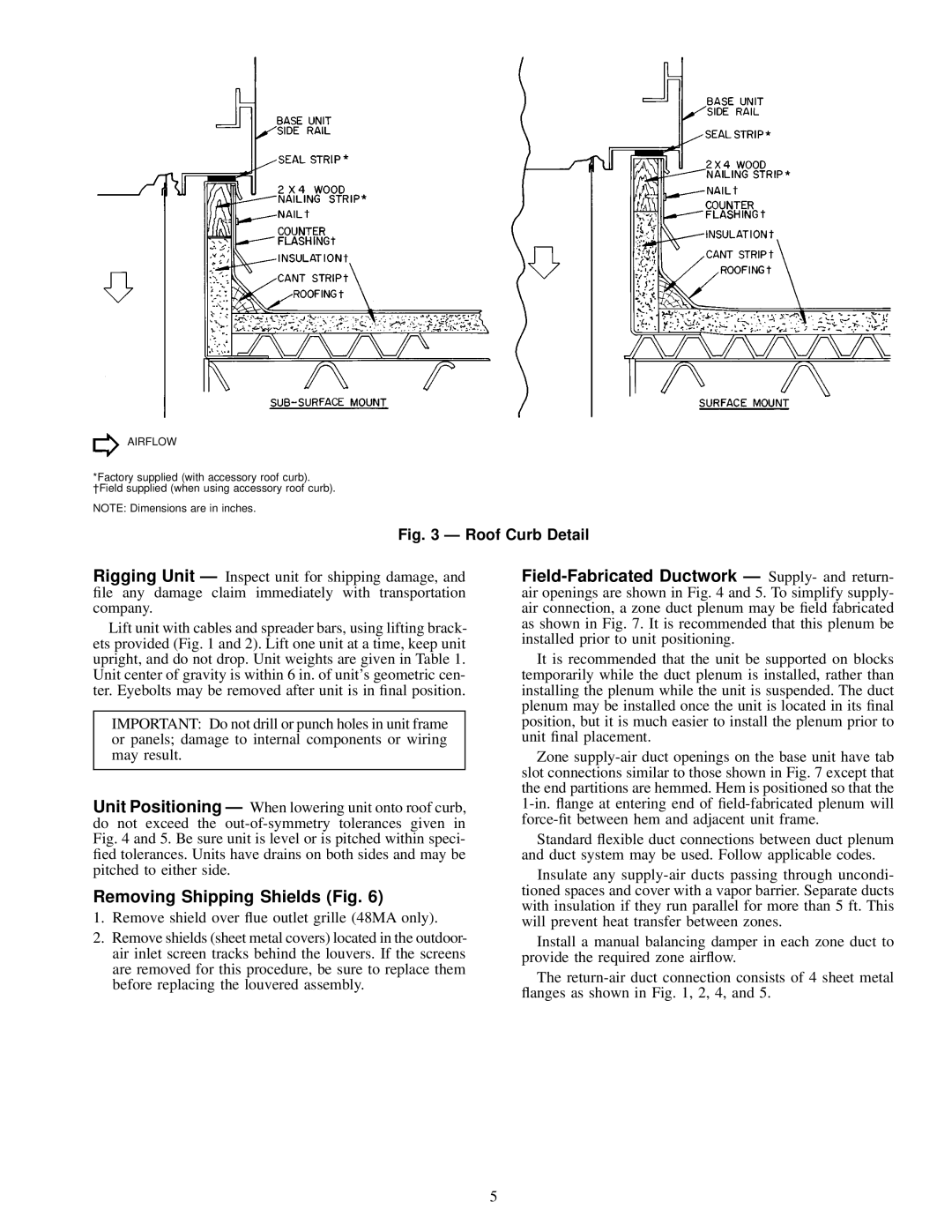
AIRFLOW

*Factory supplied (with accessory roof curb). ²Field supplied (when using accessory roof curb).

NOTE: Dimensions are in inches.

Fig. 3 Ð Roof Curb Detail

Rigging Unit Ð Inspect unit for shipping damage, and ®le any damage claim immediately with transportation company.

Lift unit with cables and spreader bars, using lifting brack- ets provided (Fig. 1 and 2). Lift one unit at a time, keep unit upright, and do not drop. Unit weights are given in Table 1. Unit center of gravity is within 6 in. of unit's geometric cen- ter. Eyebolts may be removed after unit is in ®nal position.

IMPORTANT: Do not drill or punch holes in unit frame or panels; damage to internal components or wiring may result.

Unit Positioning Ð When lowering unit onto roof curb, do not exceed the out-of-symmetry tolerances given in Fig. 4 and 5. Be sure unit is level or is pitched within speci- ®ed tolerances. Units have drains on both sides and may be pitched to either side.

Removing Shipping Shields (Fig. 6)

1.Remove shield over ¯ue outlet grille (48MA only).

2.Remove shields (sheet metal covers) located in the outdoor- air inlet screen tracks behind the louvers. If the screens are removed for this procedure, be sure to replace them before replacing the louvered assembly.

Field-Fabricated Ductwork Ð Supply- and return- air openings are shown in Fig. 4 and 5. To simplify supply- air connection, a zone duct plenum may be ®eld fabricated as shown in Fig. 7. It is recommended that this plenum be installed prior to unit positioning.

It is recommended that the unit be supported on blocks temporarily while the duct plenum is installed, rather than installing the plenum while the unit is suspended. The duct plenum may be installed once the unit is located in its ®nal position, but it is much easier to install the plenum prior to unit ®nal placement.

Zone supply-air duct openings on the base unit have tab slot connections similar to those shown in Fig. 7 except that the end partitions are hemmed. Hem is positioned so that the 1-in. ¯ange at entering end of ®eld-fabricated plenum will force-®t between hem and adjacent unit frame.

Standard ¯exible duct connections between duct plenum and duct system may be used. Follow applicable codes.

Insulate any supply-air ducts passing through uncondi- tioned spaces and cover with a vapor barrier. Separate ducts with insulation if they run parallel for more than 5 ft. This will prevent heat transfer between zones.

Install a manual balancing damper in each zone duct to provide the required zone air¯ow.

The return-air duct connection consists of 4 sheet metal ¯anges as shown in Fig. 1, 2, 4, and 5.

5

Page 5
Image 5
Carrier 48MA/50ME016-040 specifications Removing Shipping Shields Fig, Roof Curb Detail

48MA/50ME016-040 specifications

The Carrier 48MA/50ME016-040 series represents a significant advancement in the field of commercial HVAC systems, designed to provide reliable, efficient, and effective climate control solutions for various applications. These units are widely recognized for their durability and performance, making them a top choice for building owners and managers seeking optimal comfort and energy efficiency.

One of the main features of the Carrier 48MA/50ME series is its advanced scroll compressor technology. The scroll compressors are known for their reliability and efficiency, which leads to reduced energy consumption and lower operating costs. This high-efficiency design not only contributes to significant energy savings but also minimizes noise levels, enhancing the overall comfort of the environment.

The units are equipped with a unique microprocessor-based control system that offers precise temperature control and flexibility. This technology allows for easy integration with building management systems, enabling users to monitor and control their HVAC systems remotely, thereby optimizing performance and energy use. The programmable thermostats help to tailor the operation of the units to meet the specific needs of the users, ensuring maximum comfort at all times.

In addition to its robust performance features, the Carrier 48MA/50ME series also boasts a comprehensive line of options for customization. These options include various cooling capacities ranging from 16 to 40 tons, allowing the equipment to cater to different building sizes and requirements. The series is also designed with a compact footprint, making it suitable for rooftop installations where space is at a premium.

Another important characteristic of the series is its environmentally friendly refrigerant options. Carrier prioritizes the use of refrigerants with low global warming potential, contributing to a more sustainable approach to HVAC solutions. This commitment to environmental responsibility not only complies with regulations but also meets the increasing demand for greener technologies.

Furthermore, the robust construction of the Carrier 48MA/50ME series ensures long-lasting performance in even the harshest conditions. The units are designed to withstand various environmental factors, making them ideal for both commercial and industrial applications. Overall, the Carrier 48MA/50ME016-040 series stands out as a reliable choice for efficient and effective heating and cooling solutions, equipped with innovative technologies that prioritize performance, sustainability, and user comfort.