50PG03-16 specifications
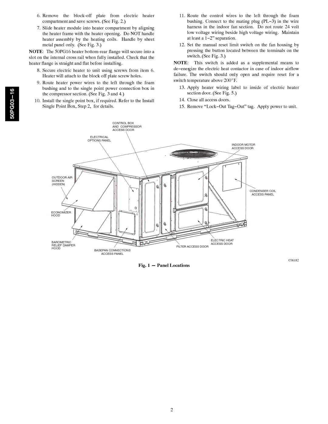
The Carrier 50PG03-16 is a notable air conditioning unit designed for residential and light commercial applications. This model stands out due to its combination of efficiency, durability, and innovative technology, making it a popular choice among homeowners and businesses looking for reliable cooling solutions.One of the primary features of the Carrier 50PG03-16 is its high energy efficiency ratio (EER). This model meets or exceeds the latest environmental standards, which is essential for users looking to reduce their energy consumption and lower utility bills. The unit's efficient refrigerant cycle maximizes cooling output while minimizing energy use.
Carrier's commitment to using advanced technology is evident in the design of the 50PG03-16. The unit is equipped with a highly reliable scroll compressor, which not only operates quietly but also enhances the overall performance and longevity of the system. This type of compressor offers improvements in energy efficiency and reduces maintenance needs, providing peace of mind to the end user.
Another significant characteristic of the Carrier 50PG03-16 is its robust construction. The cabinet is fabricated from high-quality galvanized steel, ensuring durability and resistance to corrosion. This enhances the unit's lifespan and protects it from various environmental factors, which is particularly beneficial in regions with harsh weather conditions.
The ease of installation is another plus with this model. Designed with installers in mind, the Carrier 50PG03-16 simplifies the setup process, allowing for quick and efficient installation. This feature reduces overall labor costs while ensuring that the unit operates optimally from the start.
Furthermore, the Carrier 50PG03-16 offers compatibility with a variety of controls and accessories, allowing homeowners to tailor their system for maximum comfort. Users can integrate smart thermostats and zoning options, promoting enhanced control over indoor climates.
In conclusion, the Carrier 50PG03-16 air conditioning unit is a leading choice for those seeking an efficient, reliable, and durable cooling solution. With its innovative compressor technology, robust construction, and flexible installation features, it is designed to meet the demands of both residential and light commercial applications, ensuring a comfortable environment year-round.

