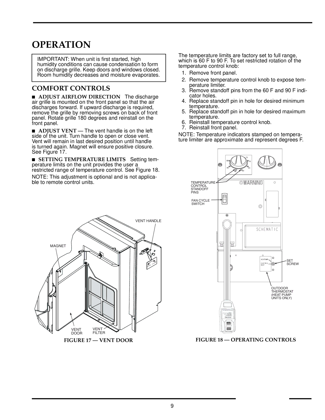
52P specifications
The Carrier 52P is a high-performance air conditioning unit that has gained popularity for its reliability and efficiency. Designed for both residential and commercial applications, the 52P is known for its superior cooling capabilities and energy-saving features, making it an attractive choice for temperature control in diverse environments.One of the standout features of the Carrier 52P is its advanced inverter technology. This technology allows the compressor to operate at variable speeds, adjusting its output to maintain the desired temperature with minimal energy consumption. This not only leads to significant energy savings but also ensures a consistent and comfortable indoor climate without the fluctuations often associated with traditional systems.
The Carrier 52P is equipped with a highly efficient rotary compressor that enhances overall performance. This compressor is designed for quiet operation, ensuring that noise levels are kept to a minimum, which is especially valuable in residential settings where noise can disrupt daily activities. Additionally, the unit is designed with a high SEER (Seasonal Energy Efficiency Ratio) rating, further emphasizing its energy-efficient nature.
In terms of design, the Carrier 52P features a modern and sleek exterior, allowing it to blend seamlessly with various architectural styles. Its compact size makes it easy to install in tight spaces while still offering robust cooling capabilities. The unit is also built with durable materials to withstand a range of weather conditions, ensuring long-lasting performance.
The 52P incorporates a sophisticated air filtration system that helps improve indoor air quality by trapping dust, allergens, and other particles. This is particularly beneficial for allergy sufferers or individuals with respiratory conditions, as it promotes healthier living environments.
Further enhancing user convenience, the Carrier 52P comes with smart connectivity options, allowing users to control their systems remotely via smartphone apps. This feature enables homeowners to adjust temperatures and monitor energy usage, providing enhanced control and flexibility.
In summary, the Carrier 52P is a technologically advanced air conditioning unit that emphasizes energy efficiency, quiet operation, and modern design. Its inverter technology and high SEER rating make it an excellent choice for those looking to reduce their energy bills while maintaining a comfortable indoor environment. With its user-friendly features and reliable performance, the Carrier 52P stands out in the market for air conditioning solutions.

