HS070-160 specifications
The Carrier HS070-160 is a high-efficiency air conditioning unit renowned for its robust performance and advanced technological features, making it an optimal choice for both commercial and industrial applications. This model is a part of Carrier's commitment to providing reliable and energy-efficient climate control solutions tailored to meet diverse cooling needs.One of the standout features of the HS070-160 is its impressive cooling capacity, which ranges from 70 to 160 tons. This range makes it suitable for various environments, from large office buildings to manufacturing facilities. The unit is designed with versatility in mind, offering the option for both air-cooled and water-cooled configurations, thereby allowing users to choose the most suitable setup for their specific installation needs.
The HS070-160 incorporates a state-of-the-art variable speed drive technology, which enables the compressor to adjust its speed according to the cooling demand. This not only results in enhanced energy efficiency but also improves overall comfort by providing more consistent temperature control. Additionally, the unit features high-efficiency scroll compressors that further improve its performance while minimizing energy consumption.
In terms of construction and durability, the HS070-160 is built to withstand harsh environmental conditions. The unit is equipped with corrosion-resistant coatings and sturdy components, ensuring longevity and reliable operation across a broad range of settings. The design also promotes ease of maintenance, with accessible service points that simplify routine checks and repairs.
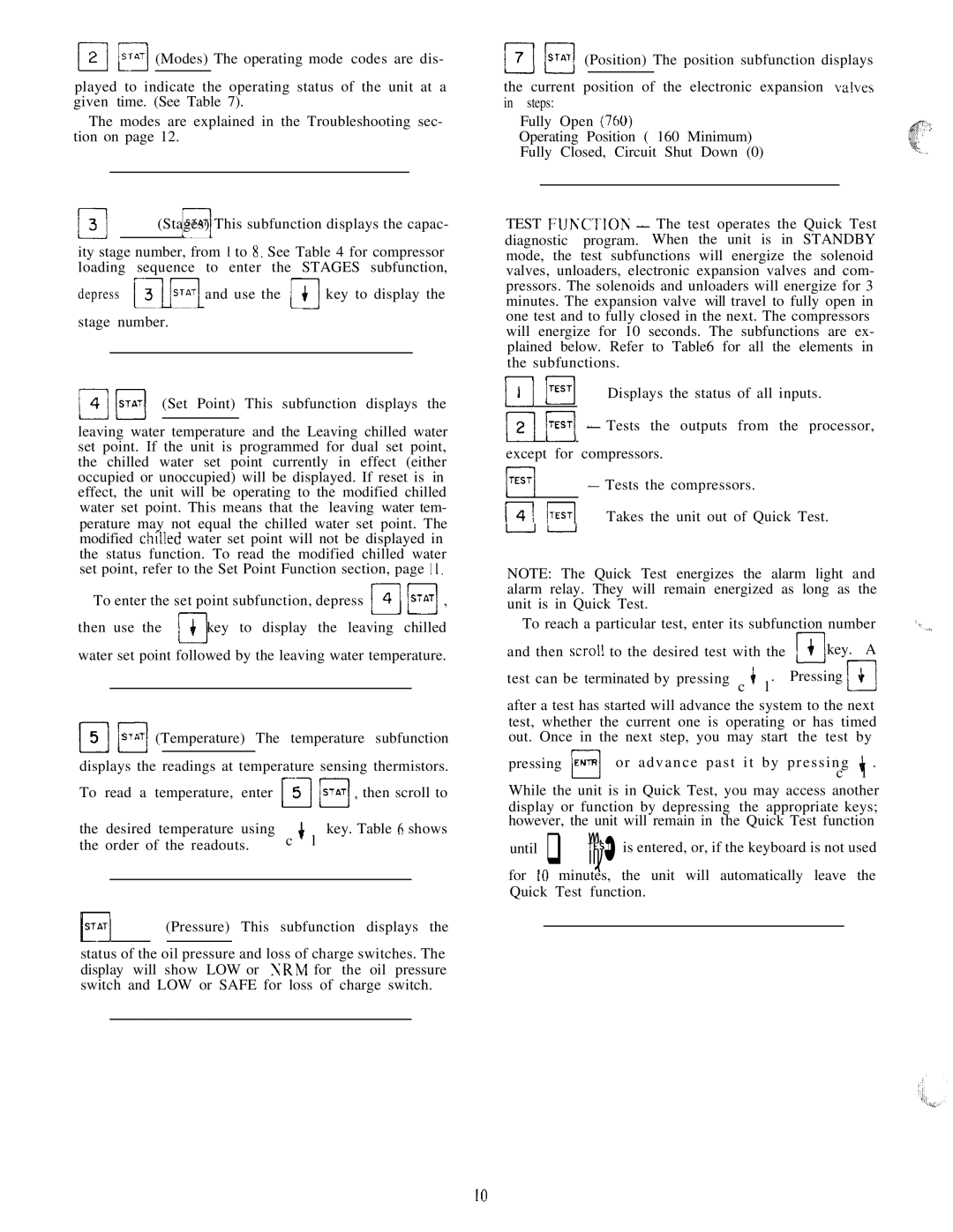
Another noteworthy characteristic of the Carrier HS070-160 is its advanced control systems. The unit can be integrated with smart building management systems, allowing for precise monitoring and control of HVAC operations. This integration helps facility managers optimize energy usage and reduce operational costs while maintaining comfortable indoor climates.
Furthermore, the HS070-160 adheres to stringent environmental standards, making it an eco-friendly choice. It is compatible with low-GWP refrigerants, aligning with global efforts to reduce greenhouse gas emissions.
In conclusion, the Carrier HS070-160 combines efficiency, durability, and advanced technology, making it a top contender for businesses looking to invest in dependable air conditioning solutions. Its comprehensive features and characteristics not only enhance performance but also contribute to significant energy savings and environmental sustainability.

