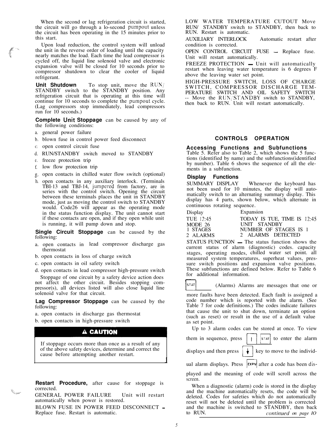
Carrier HS070-160 manual Controls Operation

Models: HS070-160

1 28
Download 28 pages 34.06 Kb
Page 5
Image 5

When the second or lag refrigeration circuit is started, the circuit will go through a lo-second pumpout unless the circuit has been operating in the 15 minutes prior to this start.

Upon load reduction, the control system will unload the unit in the reverse order of loading until the capacity nearly matches the load. Each time the lead compressor is cycled off, the liquid line solenoid valve and electronic expansion valve will be closed for 10 seconds prior to compressor shutdown to clear the cooler of liquid refrigerant.

Unit Shutdown - To stop unit, move the RUN/ STANDBY switch to the STANDBY position. Any refrigeration circuit that is operating at this time will continue for 10 seconds to complete the pumpout cycle. (Lag compressors stop immediately, lead compressors run for 10 seconds.)

Complete Unit Stoppage can be caused by any of the following conditions:

a.general power failure

b.blown fuse in control power feed disconnect

C.open control circuit fuse

d. RUN/STANDBY switch moved to STANDBY e . freeze protection trip

f.low flow protection trip

g.open contacts in chilled water flow switch (optional)

h.open contacts in any auxiliary interlock. (Terminals TBI-13 and TBJ-14, jumpered from factory, are in series with the control switch. Opening the circuit between these terminals places the unit in STANDBY mode, just as moving the control switch to STANDBY would. Code26 will appear as the operating mode

in the status function display. The unit cannot start if these contacts are open, and if they open while unit is running, it will pump down and stop.

Single Circuit Stoppage can be caused by the following:

a. open contacts in lead compressor discharge gas thermostat

b. open contacts in loss of charge switch c. open contacts in oil safety switch

d. open contacts in lead compressor high-pressure switch

Stoppage of one circuit by a safety device action does not affect the other circuit. Besides stopping com- pressor(s), all devices listed will also close liquid line solenoid valve for that circuit.

Lag Compressor Stoppage can be caused by the following:

a. open contacts in discharge gas thermostat b. open contacts in high-pressure switch

If stoppage occurs more than once as a result of any of the above safety devices, determine and correct the cause before attempting another restart.

Restart Procedure, after cause for stoppage is corrected.

GENERAL POWER FAILURE ~ Unit will restart automatically when power is restored.

BLOWN FUSE IN POWER FEED DISCONNECT ~ Replace fuse. Restart is automatic.

LOW WATER TEMPERATURE CUTOUT Move

RUN/ STANDBY switch to STANDBY, then back to RUN. Restart is automatic.

AUXILIARY INTERLOCK ~- Automatic restart after condition is corrected.

OPEN CONTROL CIRCUIT FUSE “-- Replace fuse. Unit will restart automatically.

FREEZE PROTECTION - Unit will automatically restart when leaving water temperature is 6 degrees F above the leaving water set point.

HIGH-PRESSURE SWITCH, LOSS OF CHARGE S W I T C H , C O M P R E S S O R D I S C H A R G E T E M - PERATURE SWITCH AND OIL SAFETY SWITCH

--Move the RUN;‘STANDBY switch to STANDBY, then back to RUN. Unit will restart automatically.

CONTROLS OPERATION

Accessing Functions and Subfunctions - Table 5. Refer also to Table 2, which shows the 5 func- tions (identified by name) and the subfunctions(identified by number). Table 6 shows the sequence of all the ele- ments in a subfunction.

Display Functions

SUMMARY DISPLAY ~ Whenever the keyboard has not been used for 10 minutes, the display will auto- matically switch to an alternating summary display. This display has 4 parts, shown below, which alternate in continuous rotating sequence.

Display

Expansion

TUE 12:45

TODAY IS TUE, TIME IS 12:45

MODE 26

UNIT STANDBY

1 STAGES

NUMBER OF STAGES IS 1

2 ALARMS

2 ALARMS DETECTED

STATUS FUNCTION ~ The status function shows the current status of alarm (diagnostic) codes. capacity stages, operating modes, chilled water set point. all measured system temperatures, superheat values, pres- sure switch positions and expansion valve positions. These subfunctions are defined below. Refer to Table 6 for additional information.

[rpq-r-j (Alarms) Alarms are messages that one or

more faults have been detected. Each fault is assigned a code number which is reported with the alarm. (See Table 7 for code definitions.) The codes indicate failures that cause the unit to shut down, terminate an option (such as reset) or result in the use of a default value as set point.

Up to 3 alarm codes can be stored at once. To view

them in sequence, press m m to enter the alarm

displays and then press key to move to the individ-

ual alarm displays. Press EXPN) after a code has been dis-

I

played and the meaning of code will scroll across the screen.

When a diagnostic (alarm) code is stored in the display and the machine automatically resets, the code will be deleted. Codes for safeties which do not automatically reset will not be deleted until the problem is corrected and the machine is switched to STANDBY, then back

to RUN.

confinued on page IO


5

Page 5
Image 5
Carrier HS070-160 manual Controls Operation

HS070-160 specifications

The Carrier HS070-160 is a high-efficiency air conditioning unit renowned for its robust performance and advanced technological features, making it an optimal choice for both commercial and industrial applications. This model is a part of Carrier's commitment to providing reliable and energy-efficient climate control solutions tailored to meet diverse cooling needs.

One of the standout features of the HS070-160 is its impressive cooling capacity, which ranges from 70 to 160 tons. This range makes it suitable for various environments, from large office buildings to manufacturing facilities. The unit is designed with versatility in mind, offering the option for both air-cooled and water-cooled configurations, thereby allowing users to choose the most suitable setup for their specific installation needs.

The HS070-160 incorporates a state-of-the-art variable speed drive technology, which enables the compressor to adjust its speed according to the cooling demand. This not only results in enhanced energy efficiency but also improves overall comfort by providing more consistent temperature control. Additionally, the unit features high-efficiency scroll compressors that further improve its performance while minimizing energy consumption.

In terms of construction and durability, the HS070-160 is built to withstand harsh environmental conditions. The unit is equipped with corrosion-resistant coatings and sturdy components, ensuring longevity and reliable operation across a broad range of settings. The design also promotes ease of maintenance, with accessible service points that simplify routine checks and repairs.

Another noteworthy characteristic of the Carrier HS070-160 is its advanced control systems. The unit can be integrated with smart building management systems, allowing for precise monitoring and control of HVAC operations. This integration helps facility managers optimize energy usage and reduce operational costs while maintaining comfortable indoor climates.

Furthermore, the HS070-160 adheres to stringent environmental standards, making it an eco-friendly choice. It is compatible with low-GWP refrigerants, aligning with global efforts to reduce greenhouse gas emissions.

In conclusion, the Carrier HS070-160 combines efficiency, durability, and advanced technology, making it a top contender for businesses looking to invest in dependable air conditioning solutions. Its comprehensive features and characteristics not only enhance performance but also contribute to significant energy savings and environmental sustainability.