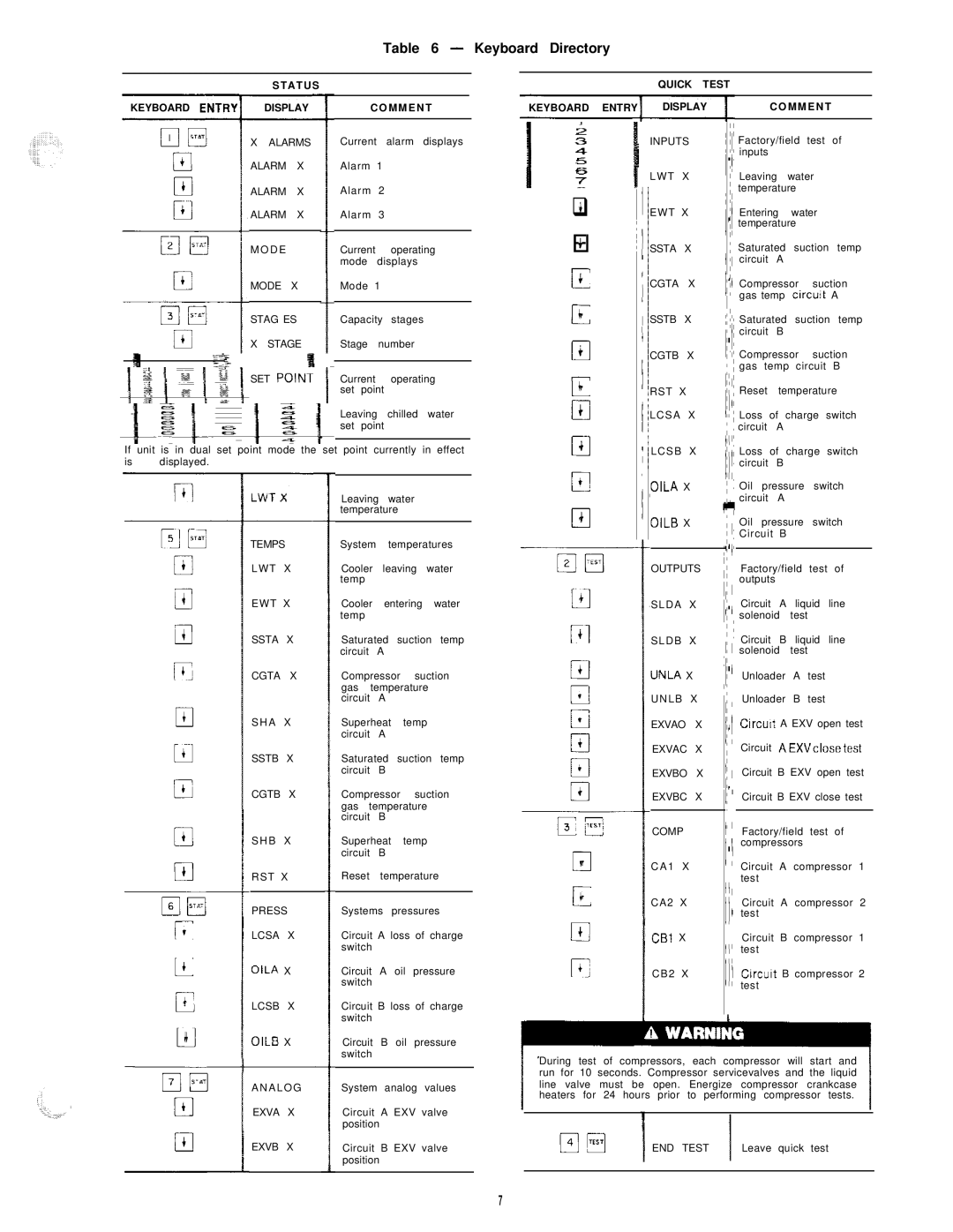
Table 6 - Keyboard Directory

S T A T U S

KEYBOARD ENTI DISPLAYC O M M E N T

QUICK TEST

KEYBOARD ENTRY

DISPLAY

C O M M E N T


X ALARMS Current alarm displays

ALARM X Alarm 1

ALARM X Alarm 2

ALARM X Alarm 3

M O D ECurrent operating mode displays

MODE X Mode 1

STAG ES

Capacity stages

X STAGE Stage number

SET POlNT Current operating set point

Leaving chilled water set point

If unit is in dual set point mode the set point currently in effect

is displayed. ’


Leaving water


temperature


TEMPS

System

temperatures


L W T

X

Cooler

leaving water

i


temp


EWT

X

Cooler

entering

water

0


temp


i


SSTA

X

Saturated

suction

temp

G


circuit


A


CGTA

X

Compressor

suction


gas

temperature


circuit

A


4

S H A

X

Superheat

temp


17


circuit

A


SSTB

X

Saturated

suction

temp


circuit

B


CGTB

X

Compressor

suction


gas

temperature


circuit

B


S H B

X

Superheat

temp


circuit

B


RST

X

Reset

temperature


PRESS

Systems

pressures


LCSA

X

Circuit A loss of charge


switch


+

OILA

X

Circuit

A

oil

pressure


switch


LCSB

X

Circuit B loss of charge

c


$


switch


OILB

X

Circuit

B

oil

pressure

Cl


switch


q4

El+ r=c 0c

0+

0c cl4

illc

0t

El4

cl4

04

c4

INPUTS

L W T X

EWT X

SSTA X

CGTA X

SSTB X

CGTB X

RST X

LCSA X

LCSB X

OILA X

OILB X

OUTPUTS

SLDA X

SLDB X

UNLA X

U N L B X

EXVAO X

EXVAC X

EXVBO X

EXVBC X

COMP

C A 1 X

CA2 X

CBI X

CB2 X

Factory/field test of inputs

Leaving water temperature

Entering water temperature

Saturated suction temp circuit A

Compressor suction gas temp circuit A

Saturated suction temp circuit B

Compressor suction gas temp circuit B

Reset temperature

Loss of charge switch circuit A

Loss of charge switch circuit B

Oil pressure switch circuit A

Oil pressure switch Circuit B

Factory/field test of outputs

Circuit A liquid line solenoid test

Circuit B liquid line solenoid test

Unloader A test

Unloader B test

Circurt A EXV open test

Circuit AEXVclosetest

Circuit B EXV open test

Circuit B EXV close test

Factory/field test of compressors

Circuit A compressor 1 test

Circuit A compressor 2 test

Circuit B compressor 1 test

Circuit B compressor 2 test

A N A L O G

System analog values

EXVA X

Circuit

A EXV valve


position

EXVB X

Circuit

B EXV valve


position


During test of compressors, each compressor will start and run for 10 seconds. Compressor servicevalves and the liquid line valve must be open. Energize compressor crankcase heaters for 24 hours prior to performing compressor tests.

p-Jm

END TEST

Leave quick test


I


7

Page 7
Image 7
Carrier HS070-160 manual El4

HS070-160 specifications

The Carrier HS070-160 is a high-efficiency air conditioning unit renowned for its robust performance and advanced technological features, making it an optimal choice for both commercial and industrial applications. This model is a part of Carrier's commitment to providing reliable and energy-efficient climate control solutions tailored to meet diverse cooling needs.

One of the standout features of the HS070-160 is its impressive cooling capacity, which ranges from 70 to 160 tons. This range makes it suitable for various environments, from large office buildings to manufacturing facilities. The unit is designed with versatility in mind, offering the option for both air-cooled and water-cooled configurations, thereby allowing users to choose the most suitable setup for their specific installation needs.

The HS070-160 incorporates a state-of-the-art variable speed drive technology, which enables the compressor to adjust its speed according to the cooling demand. This not only results in enhanced energy efficiency but also improves overall comfort by providing more consistent temperature control. Additionally, the unit features high-efficiency scroll compressors that further improve its performance while minimizing energy consumption.

In terms of construction and durability, the HS070-160 is built to withstand harsh environmental conditions. The unit is equipped with corrosion-resistant coatings and sturdy components, ensuring longevity and reliable operation across a broad range of settings. The design also promotes ease of maintenance, with accessible service points that simplify routine checks and repairs.

Another noteworthy characteristic of the Carrier HS070-160 is its advanced control systems. The unit can be integrated with smart building management systems, allowing for precise monitoring and control of HVAC operations. This integration helps facility managers optimize energy usage and reduce operational costs while maintaining comfortable indoor climates.

Furthermore, the HS070-160 adheres to stringent environmental standards, making it an eco-friendly choice. It is compatible with low-GWP refrigerants, aligning with global efforts to reduce greenhouse gas emissions.

In conclusion, the Carrier HS070-160 combines efficiency, durability, and advanced technology, making it a top contender for businesses looking to invest in dependable air conditioning solutions. Its comprehensive features and characteristics not only enhance performance but also contribute to significant energy savings and environmental sustainability.