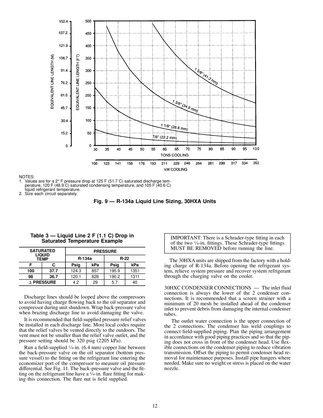
30HXA, HXC076-186 specifications
The Carrier 30HXA and 30HXC series is a notable line of chillers designed for commercial applications, providing advanced cooling solutions for various buildings and infrastructures. These models are known for their reliability and efficiency, making them a preferred choice for building managers and facilities engineers.One of the key features of the Carrier 30HXA and 30HXC series is their use of high-efficiency, variable-speed scroll compressors. This technology allows the chillers to adjust their cooling output based on the actual demand, resulting in significant energy savings, especially during periods of partial load. This responsiveness not only leads to lower operational costs but also reduces wear and tear on the equipment, extending its lifespan.
Another critical aspect of these chillers is their eco-friendly refrigerant options. The 30HXA and 30HXC models utilize R-410A refrigerant, which has a lower environmental impact compared to traditional refrigerants. This commitment to sustainability aligns with modern regulations and climate goals, making these chillers an environmentally responsible choice.
Both series offer a wide range of cooling capacities, from 76,000 to 186,000 BTU/h, catering to various commercial needs. The compact design and modular configurations of these chillers allow for easy installation and integration into existing systems, facilitating retrofits and upgrades without significant disruption.
The 30HXA and 30HXC chillers also feature advanced controls that enhance their operational efficiency. The integrated controls allow for easy monitoring and adjustments, enabling users to optimize performance and minimize energy consumption. Additionally, they can easily interface with building management systems (BMS), providing real-time data and improved operational insights.
Durability is another hallmark of the Carrier 30HXA and 30HXC series. Built with corrosion-resistant materials and designed to withstand harsh weather conditions, these chillers ensure reliable performance in various environments. The robust construction further enhances their longevity, providing consistent cooling solutions for years.
In summary, the Carrier 30HXA and 30HXC series chillers offer advanced technology, eco-friendly refrigerants, energy efficiency through variable-speed compressors, and durable construction. These features come together to provide a reliable and effective cooling solution for a wide range of commercial applications, ensuring comfort and performance while supporting sustainability goals.

