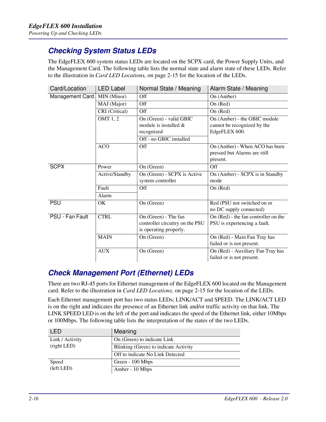
600, EdgeFLEX specifications
Carrier Access EdgeFLEX 600 is an advanced solution designed to cater to the growing demands of telecom operators and large enterprises. This versatile platform seamlessly integrates various technologies to provide robust connectivity, enhanced network performance, and operational efficiency. With its cutting-edge features, EdgeFLEX 600 is poised to play a critical role in the evolution of modern communication networks.One of the standout features of EdgeFLEX 600 is its remarkable scalability. Engineered to support a wide range of applications, the platform can be easily expanded to meet the increasing bandwidth requirements of users. This scalability is particularly crucial for service providers aiming to accommodate the influx of data traffic generated by the rise of IoT devices and high-definition content streaming.
EdgeFLEX 600 is equipped with a powerful multi-service architecture, making it ideal for a variety of deployment scenarios. This architecture allows operators to deliver voice, video, and data services over a single platform, significantly reducing operational costs and simplifying network management. The platform supports various protocols, including Ethernet, MPLS, and SDH, ensuring compatibility with existing infrastructures and facilitating smooth integration.
The user experience is further enhanced by EdgeFLEX 600's advanced Quality of Service (QoS) features. These capabilities enable operators to prioritize critical applications and allocate bandwidth dynamically, ensuring optimal performance under varying network conditions. Furthermore, built-in analytics and monitoring tools provide valuable insights into network performance, enabling proactive troubleshooting and efficient resource management.
Security is also a top priority for EdgeFLEX 600. The platform incorporates robust encryption and authentication protocols to safeguard sensitive data and prevent unauthorized access. This focus on security is essential in an era where cyber threats are increasingly sophisticated and prevalent.
In terms of energy efficiency, EdgeFLEX 600 has been designed with sustainability in mind. Its optimized hardware and software components work together to minimize power consumption, thereby reducing operational costs and the overall environmental footprint of communication networks.
In summary, Carrier Access EdgeFLEX 600 is a cutting-edge solution that addresses the modern challenges faced by telecom operators and enterprises. With its scalable architecture, multi-service capabilities, advanced QoS features, strong security, and energy efficiency, EdgeFLEX 600 is well-equipped to support the next generation of communication networks. As the demand for high-performance connectivity continues to grow, this platform will undoubtedly play a pivotal role in shaping the future of telecommunications.

