Manuals
/
Carrier Access
/
Computer Equipment
/
Network Card
Carrier Access
KTA Installation and Setting, LED Indicators, Application figure, Small PABX
Models:
KTA
1
4
14
14
Download
14 pages
55.06 Kb
1
2
3
4
5
6
7
8
Install
Dimension
Configuration
Page 4
Image 4
Page 3
Page 5
Page 4
Image 4
Page 3
Page 5
Contents
Adapter KTA Series User Manual
3.2.1 Configuring Network Parameters from Telephone Handset
2. Sketch
1. Introduction
2.1 Ports figure
3. Installation and Setting
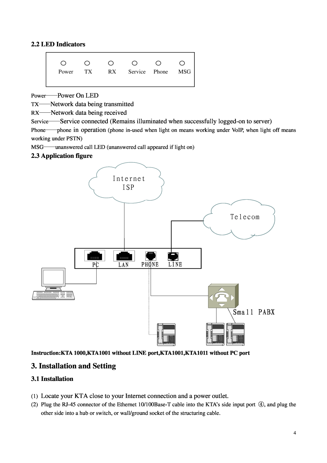
2.2 LED Indicators
3.1 Installation
2.3 Application figure
3.2.1 Configuring Network Parameters from Telephone Handset
3.2 Configuration
3.2.2 Configuring Network Parameters from Web Browser
Fill in IP
Fill in DNS
Audio codec Ringtype
4.1 Making and Receiving calls
4. Functions
Notice It is applicable to all KTA users
4.2 Use digitmap
4.3 Call Forwarding
4.1.2 Receiving
b Notice it is only for the users except from a
5. Technical Parameter
5.1 The electronic specifications
5.2 Working/storing environment
6. Frequent Problems and Solutions
5.3 Dimensions
7.1 Features
7. Appendix
7.2 Standards and agreements
7.4 Commands For Setting Network Parameters
7.3 Recommend usage net condition
Top
Page
Image
Contents