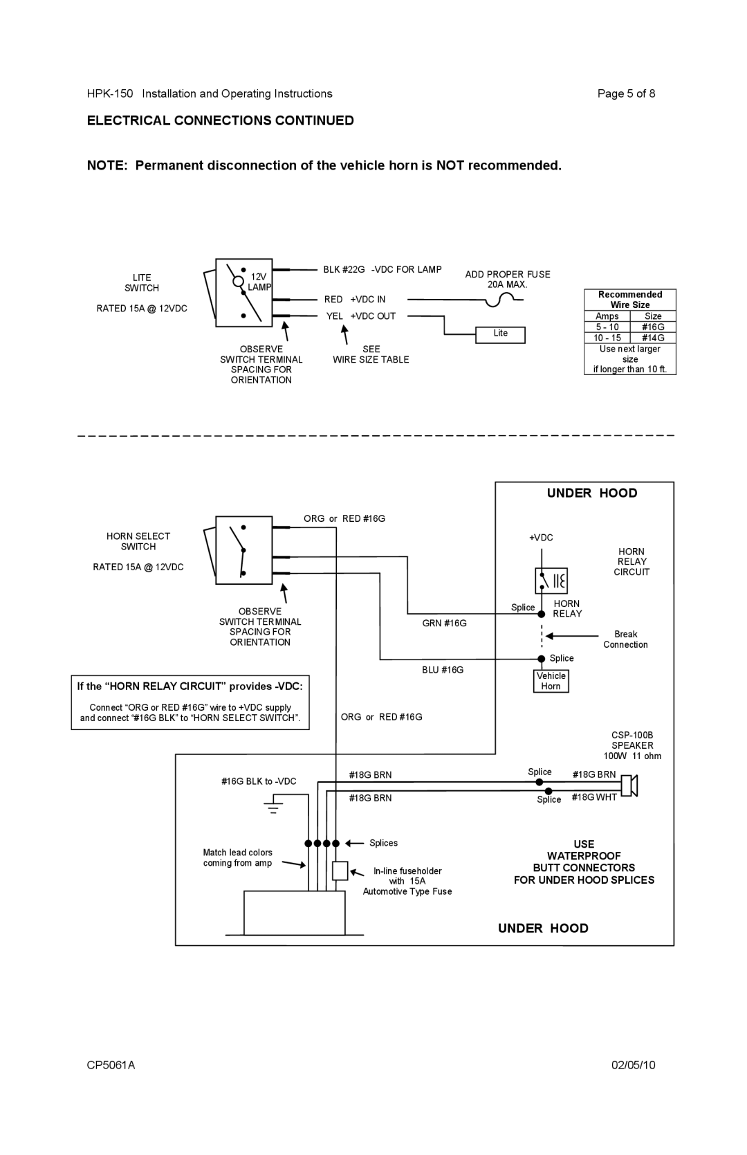
Horn System specifications
The Carson Horn System is an advanced audio technology designed to deliver exceptional sound quality in various environments, from small spaces to expansive venues. This innovative system is engineered to provide clear and balanced audio while minimizing distortion, making it an ideal choice for professional audio applications such as live performances, installations, and public address systems.One of the main features of the Carson Horn System is its unique horn design. The horn structure enhances sound dispersion and projection, allowing audio to reach a wider audience with minimal loss of quality. This makes it particularly effective in outdoor settings or large auditoriums where sound clarity is crucial. The horn design also helps to reduce feedback issues, a common challenge in live sound situations, ensuring that the sound remains crisp and intelligible.
In terms of technology, the Carson Horn System boasts cutting-edge speaker drivers that are meticulously crafted for optimal performance. These drivers are designed to handle high power levels while providing a wide frequency response, allowing for rich bass tones and clear mid and high frequencies. The integration of durable materials in the construction of the drivers ensures longevity, making the system a reliable choice for frequent use.
Another characteristic of the Carson Horn System is its versatility. It can be configured in various ways to suit different setups, whether as standalone units or in a multi-speaker array. This flexibility allows audio professionals to tailor the system to meet specific acoustical requirements while maintaining outstanding sound quality. Furthermore, the system is compatible with a wide range of amplifiers and audio processors, enabling users to integrate it seamlessly into existing setups.
The Carson Horn System also prioritizes ease of use. Setup is straightforward, with user-friendly connectors and options for both wired and wireless configurations. This design consideration reduces the complexity often associated with professional audio systems, enabling technicians to focus on performance rather than troubleshooting technical issues.
Overall, the Carson Horn System is a state-of-the-art audio solution that combines innovative horn technology, high-performance drivers, and user-friendly features to provide an unmatched sound experience. Whether in a concert hall, conference center, or outdoor festival, the Carson Horn System is engineered to meet the demands of any professional audio environment.

