FOUR SEASONS™ III (OUTSIDE USA INSTALLATION)
FAN INSTALLATION OUTSIDE THE USA - EXCLUDING MODELS ENDING IN ‘E’
If you do not have an existing fixture located where you wish to place your Casablanca fan, a new ceiling fixture outlet box
must be installed (use an outlet box marked acceptable for fan support) and an electrical cable to run it. This box must be secured to the ceiling according to the outlet box manufacturer’s instructions. It is recommended that this be done by
a qualified electrician.
Vaulted or Cathedral Ceiling Installations
Your Casablanca fan may be installed on a vaulted or cathedral ceiling in the same manner as described for a flat ceiling. The
Using Existing Ceiling Fixture Outlet Box
After turning electrical power off, lower the old fixture to expose the wiring and the ceiling fixture outlet box. Cut the fixture wires or if wire nuts have been used, unscrew them and disconnect the wires. The fixture can then be removed.
After removing the old fixture, check the outlet box to sure that it is supported by a joist or beam across its upper surface. If not, a 2" x 4" stud must be installed.
OUTSIDE USA - SECONDARY SUPPORT INSTALLATION PARTS
OUTLET |
|
|
|
|
ADAPTOR | 6" OUTLET BOX | 3 8"- 7 LAG SCREW (5") | FENDER | SPRING LOCK |
PLATE | ||||
| CABLE |
| WASHER | HOOK |
OUTSIDE USA - MOUNTING SECONDARY SUPPORT PARTS TO OUTLET BOX
1WARNING: MOUNT ONLY TO AN OUTLET BOX MARKED ACCEPTABLE FOR FAN SUPPORT
••••
ADVERTISSEMENT: ASSEMBLER UNIQUEMENT À UNE BÔITE DE SORTIE JUGÉE ACCEPTABLE POUR RETENIR UN VENTILATEUR.
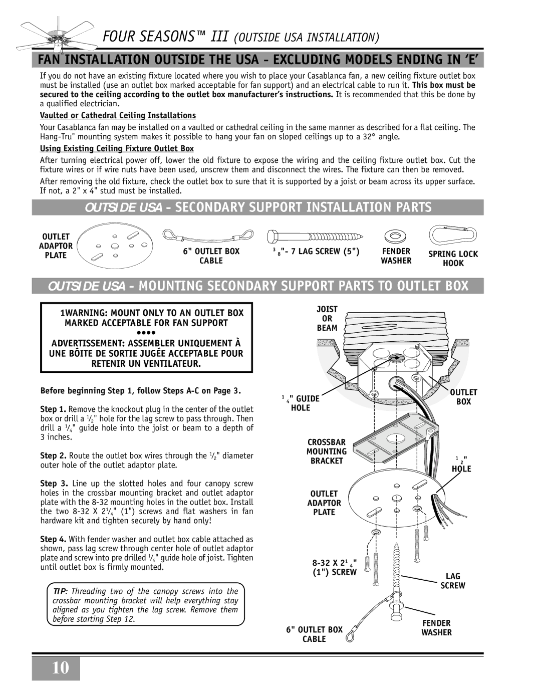
Before beginning Step 1, follow Steps A-C on Page 3.
Step 1. Remove the knockout plug in the center of the outlet box or drill a 1⁄2" hole for the lag screw to pass through. Then drill a 1⁄4" guide hole into the joist or beam to a depth of 3 inches.
Step 2. Route the outlet box wires through the 1⁄2" diameter outer hole of the outlet adaptor plate.
Step 3. Line up the slotted holes and four canopy screw holes in the crossbar mounting bracket and outlet adaptor plate with the
Step 4. With fender washer and outlet box cable attached as shown, pass lag screw through center hole of outlet adaptor plate and screw into pre drilled 1⁄4" guide hole of joist. Tighten until outlet box is firmly mounted.
TIP: Threading two of the canopy screws into the crossbar mounting bracket will help everything stay aligned as you tighten the lag screw. Remove them before starting Step 12.
JOIST
OR
BEAM
14"HOLEGUIDE
CROSSBAR
MOUNTING
BRACKET
OUTLET
ADAPTOR
PLATE
6" OUTLET BOX  CABLE
CABLE 
OUTLET
BOX
1 2"
HOLE
LAG
SCREW
FENDER
WASHER
10