2.1.2 Reference for C-MOS Imager Performance
Reference of the
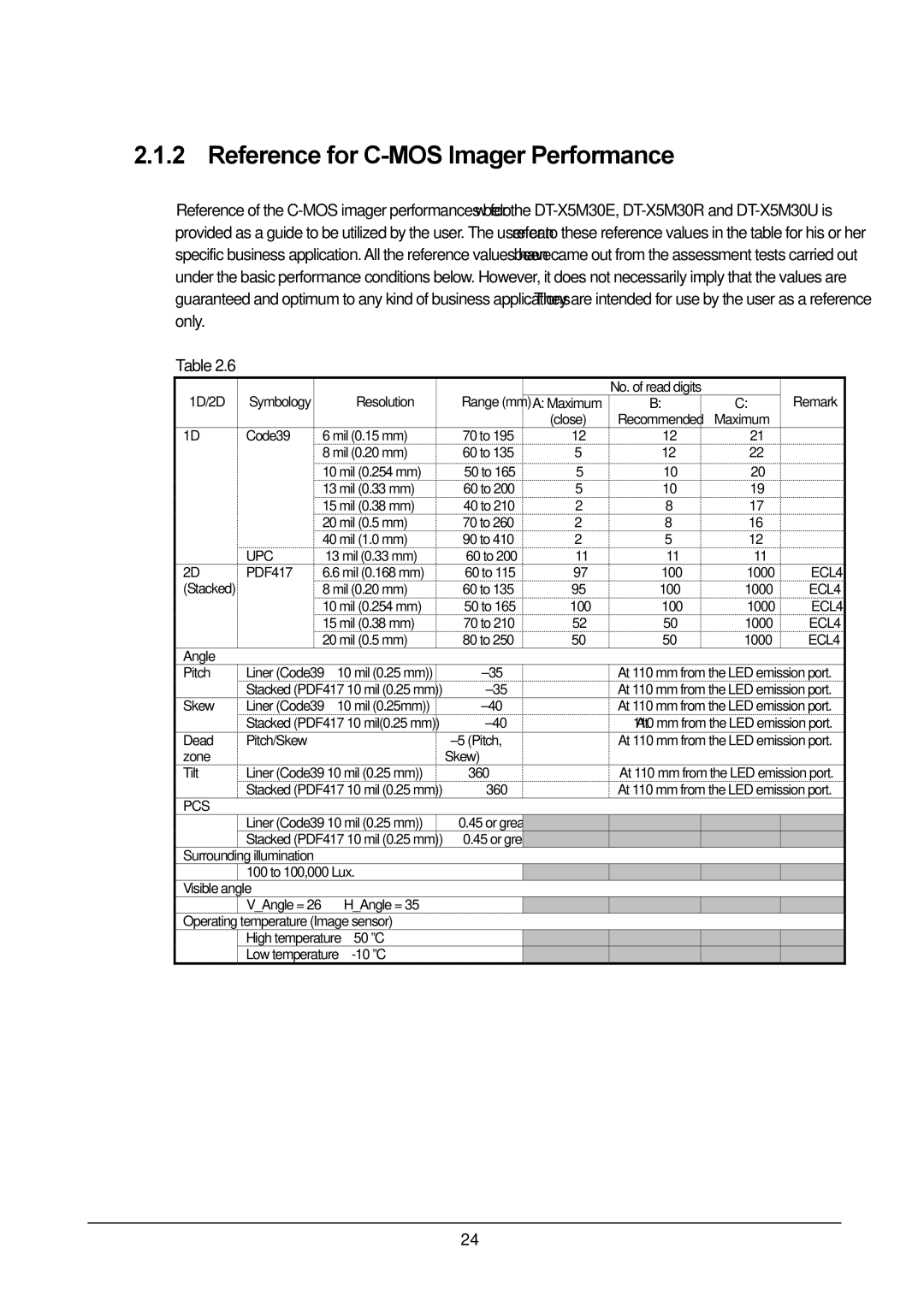
Table 2.6
1D/2D | Symbology |
|
| Resolution | Range (mm) |
| No. of read digits |
|
| Remark |
|
| A: Maximum | B: | C: |
| |||||
|
|
|
|
|
| (close) | Recommended | Maximum |
|
|
1D | Code39 |
| 6 mil (0.15 mm) | 70 to 195 | 12 | 12 | 21 |
|
| |
|
|
| 8 mil (0.20 mm) | 60 to 135 | 5 | 12 | 22 |
|
| |
|
|
| 10 mil (0.254 mm) | 50 to 165 | 5 | 10 | 20 |
|
| |
|
|
| 13 mil (0.33 mm) | 60 to 200 | 5 | 10 | 19 |
|
| |
|
|
| 15 mil (0.38 mm) | 40 to 210 | 2 | 8 | 17 |
|
| |
|
|
| 20 mil (0.5 mm) | 70 to 260 | 2 | 8 | 16 |
|
| |
|
|
| 40 mil (1.0 mm) | 90 to 410 | 2 | 5 | 12 |
|
| |
| UPC | 13 mil (0.33 mm) | 60 to 200 | 11 | 11 | 11 |
|
| ||
2D | PDF417 | 6.6 mil (0.168 mm) | 60 to 115 | 97 | 100 | 1000 |
| ECL4 | ||
(Stacked) |
|
| 8 mil (0.20 mm) | 60 to 135 | 95 | 100 | 1000 |
| ECL4 | |
|
|
| 10 mil (0.254 mm) | 50 to 165 | 100 | 100 | 1000 | ECL4 | ||
|
|
| 15 mil (0.38 mm) | 70 to 210 | 52 | 50 | 1000 |
| ECL4 | |
|
|
| 20 mil (0.5 mm) | 80 to 250 | 50 | 50 | 1000 |
| ECL4 | |
Angle |
|
|
|
|
|
|
|
|
|
|
Pitch | Liner (Code39 | 10 mil (0.25 mm)) | ±35° |
| At 110 mm from the LED emission port. | |||||
| Stacked (PDF417 10 mil (0.25 mm)) | ±35° |
| At 110 mm from the LED emission port. | ||||||
Skew | Liner (Code39 | 10 mil (0.25mm)) | ±40° |
| At 110 mm from the LED emission port. | |||||
| Stacked (PDF417 10 mil(0.25 mm)) | ±40° |
| At 110 mm from the LED emission port. | ||||||
Dead | Pitch/Skew |
|
| ±5°(Pitch, |
| At 110 mm from the LED emission port. | ||||
zone |
|
|
|
| Skew) |
|
|
|
|
|
Tilt | Liner (Code39 10 mil (0.25 mm)) | 360° |
| At 110 mm from the LED emission port. | ||||||
| Stacked (PDF417 10 mil (0.25 mm)) | 360° |
| At 110 mm from the LED emission port. | ||||||
PCS |
|
|
|
|
|
|
|
|
|
|
| Liner (Code39 10 mil (0.25 mm)) | 0.45 or greater |
|
|
|
|
| |||
| Stacked (PDF417 10 mil (0.25 mm)) | 0.45 or greater |
|
|
|
|
| |||
Surrounding | illumination |
|
|
|
|
|
|
|
| |
| 100 to 100,000 Lux. |
|
|
|
|
|
| |||
Visible angle |
|
|
|
|
|
|
|
| ||
| V_Angle = 26° |
| H_Angle = 35° |
|
|
|
|
|
| |
Operating | temperature (Image sensor) |
|
|
|
|
|
| |||
| High temperature | 50 ºC |
|
|
|
|
|
| ||
| Low temperature |
|
|
|
|
|
| |||
24