![]()
![]()
![]()
![]() ®
®
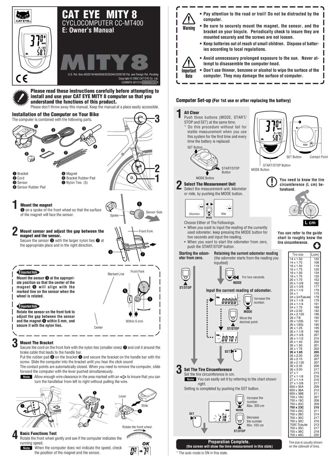
CAT EYE MITY 8
CYCLOCOMPUTER
E: Owner’s Manual
MITY8
U.S. Pat. Nos.4633216/4642606/5226340/5236759 Pat. and Design Pat. Pending
Copyright © 2002 CAT EYE Co. Ltd.
• Pay attention to the road or trail! Do not be distracted by the computer.
Warning | • Be sure to securely mount the magnet, the sensor, and the | |
bracket on your bicycle. Periodically check to insure they are | ||
| ||
| mounted securely and the screws are not loosen. |
•Keep batteries out of reach of small children. Dispose of batter- ies according to local regulations.
•Avoid unnecessary prolonged exposure to the sun. Never at-
tempt to disassemble the computer head.
Important | • Don’t use thinner, benzene or alcohol to wipe the surface of the |
Note | computer. They may damage the surface of computer. |
Please read these instructions carefully before attempting to install and use your CAT EYE MITY 8 computer so that you understand the functions of this product.
Please don’t throw away this manual, Keep the manual at a place easily accessible.
Installation of the Computer on Your Bike | 3 | |||
The computer is combined with the following parts. | ||||
| ||||
1 | 2 | 3 |
| |
|
| |||
|
|
| ||
4
6
57
Computer Set-up (For 1st use or after replacing the battery)
All Clear |
|
1 Push three buttons (MODE, START/ |
|
STOP and SET) at the same time. |
|
* Do this procedure without fail for |
|
stable measurement when you use |
|
this system for the first time and every |
|
time the battery is replaced. |
|
SET Button |
|
SET Button | Contact Point |
1 Bracket | 5 Magnet |
2 Cord | 6 Bracket Rubber Pad |
3 Sensor | 7 Nylon Ties (5) |
4Sensor Rubber Pad
1 Mount the magnet
5 on a spoke of the front wheel so that the surface of the magnet will face the sensor.
2 Mount sensor and adjust the gap between the magnet and the sensor.
Secure the sensor 3 with the larger nylon ties 7 at the appropriate place and in the right direction.
2
1
5
![]()
![]() Sensor Side Spoke
Sensor Side Spoke ![]()
![]()
Front Fork
37
| START/STOP | START/STOP Button |
| |||
| MODE Button |
|
|
|
| |
| Button |
|
|
|
| |
|
|
|
|
|
| |
MODE Button |
| ! |
| You need to know the tire | ||
Select The Measurement Unit |
|
| ||||
|
| circumference (L cm) be- | ||||
2 Select the measurement unit, kilometer |
|
|
| forehand. |
| |
or mile, by pushing the MODE button. |
|
|
|
|
| |
Kilometer | Mile |
|
|
|
|
|
| MODE |
|
|
|
|
|
Choose Either of The Followings. |
|
|
|
| L cm | |
• When you want to input the reading of the currently |
|
|
|
| ||
used odometer, keep pressing the MODE button for |
| You can refer to the guide | ||||
two seconds and input the reading. |
|
| chart to roughly know the | |||
• When you want to start the odometer from zero, |
| tire circumference. | ||||
push the START/STOP button. |
|
|
|
|
| |
Starting the odom- Retaining the current odometer reading | Tire size | L(cm) | ||||
eter from zero. | (the odometer starts from the reading you | 14 x 1.50 | 102 | |||
| inputted) |
|
|
| 14 x 1.75 | 106 |
|
|
|
|
| 16 x 1.50 | 119 |
 Important Note
Marked Line
Front Fork
16 x 1.75 | 120 |
18 x 1.50 | 134 |
Mount the sensor 3 at the appropri- ate position so that the center of the magnet 5 will align with the marked line on the sensor when the wheel is rotated.
![]() Important Note
Important Note
Rotate the sensor on the front fork to |
|
adjust the gap between the sensor |
|
and the magnet 5 within 5 mm, and |
|
secure it with the nylon ties. | Center |
|
5![]()
![]()
![]()
![]() 3
3
Within 5 mm
For two seconds. | 18 x 1.75 | 135 | |
MODE | 20 x 1.75 | 152 | |
20 x | 162 | ||
ST/STOP | 22 x | 177 | |
Input the current reading of odometer. | 22 x | 179 | |
| 24 x 1 | 175 | |
Increase the | 24 x 3/4Tubular | 178 | |
24 x | 179 | ||
number. | |||
24 x | 191 | ||
| |||
| 24 x 1.75 | 189 | |
MODE | 24 x 2.00 | 192 | |
Move the | 24 x 2.125 | 196 | |
26 x 7/8 | 192 | ||
decimal point. | 26 x 1(59) | 191 | |
| 26 x 1(65) | 195 | |
ST/STOP | 26 x 1.25 | 195 | |
| 26 x | 190 | |
| 26 x | 207 | |
| 26 x | 210 |
3 Mount The Bracket
Secure the cord on the front fork with the nylon ties (smaller ones) 7 and coil it around the brake cable that leads to the handle bar.
Put the rubber pad 6 on the bracket 1 and secure the bracket on the handle bar with the screw. Slide the computer into the bracket until you hear the click sound
The contact points are automatically closed. When you need to remove the computer, slide forward the computer with the lever pushed simultaneously.
Note Allow enough wire clearance in the area marked with an | to insure that you can | |
turn the handlebar from left to right without pulling the wire. | ||
1 | Lever | |
| ||
7 | 6 | Slide |
|
| |
|
| 1 |
|
| Rotate the front wheel. |
Basic Functions Test |
|
|
4 Rotate the front wheel gently and see if the computer indicates the |
| |
running speed. |
| OK |
Note When the computer does not indicate the speed, check |
| |
the position of the magnet and the sensor. |
|
|
|
|
|
|
|
| 26 x 1.40 | 200 |
|
|
|
|
|
|
| 26 x 1.50 | 201 |
|
|
| SET |
| 26 x 1.75 | 202 |
| ||
|
|
| 26 x 1.95 | 205 |
| |||
|
|
|
|
|
| 26 x 2.00 | 206 |
|
|
|
|
|
|
| 26 x 2.10 | 207 |
|
|
|
|
|
|
| 26 x 2.125 | 207 |
|
| Set The Tire Circumference |
| 26 x 2.35 | 208 |
| |||
|
| 26 x 3.00 | 217 |
| ||||
| 3 Set the tire circumference in cm. |
|
| 27 x 1 | 215 |
| ||
|
| |||||||
| Note You can easily set it by referring to the chart shown |
| 27 x | 216 |
| |||
|
| 27 x | 216 |
| ||||
| right. |
| 27 x | 217 |
| |||
| Setting is completed by pushing the SET button. |
| 650 x 35A | 209 |
| |||
|
| 650 x 38A | 212 |
| ||||
|
|
|
|
|
|
| ||
|
|
|
|
|
| 650 x 38B | 211 |
|
|
|
| Increase the |
| 700 x 18C | 207 |
| |
|
|
| number. |
| 700 x 19C | 208 |
| |
|
|
|
| 700 x 20C | 209 |
| ||
|
|
| Max. 300 cm |
|
| |||
|
|
|
| 700 x 23C | 210 |
| ||
|
| MODE |
|
| ||||
|
|
| 700 x 25C | 211 |
| |||
| SET |
| 700 x 28C | 214 |
| |||
|
|
| Decrease |
| 700 x 30C | 217 |
| |
|
|
| the number |
| 700 x 32C | 216 |
| |
|
|
| Min. 100 cm |
| 700C Tubular | 213 |
| |
|
| ST/STOP |
| 700 x 35C | 217 |
| ||
|
|
| 700 x 38C | 218 |
| |||
|
|
|
|
|
| 700 x 40C | 220 |
|
| Preparation Complete. |
|
|
| ||||
|
| Tire size is usually shown | ||||||
| (the screen will show the time measurement in this state) |
| on the sidewall of tires. | |||||
* The auto mode is ON in this state.