5.Video Output
This jack accepts the yellow RCA plug and applies the video signal to the user monitor; (Example LCM4000, LCM5600 etc.). Use the Control Sta- tion Source Cable (CSSC).
6.Monitor 1 (12VDC Output)
This jack accepts the black barrel type power con- nector from the Control Station Source Cable. This
supplies power to the user monitor.
7.Station 1 controller (8-pin DIN Jack)
This
Note: Items
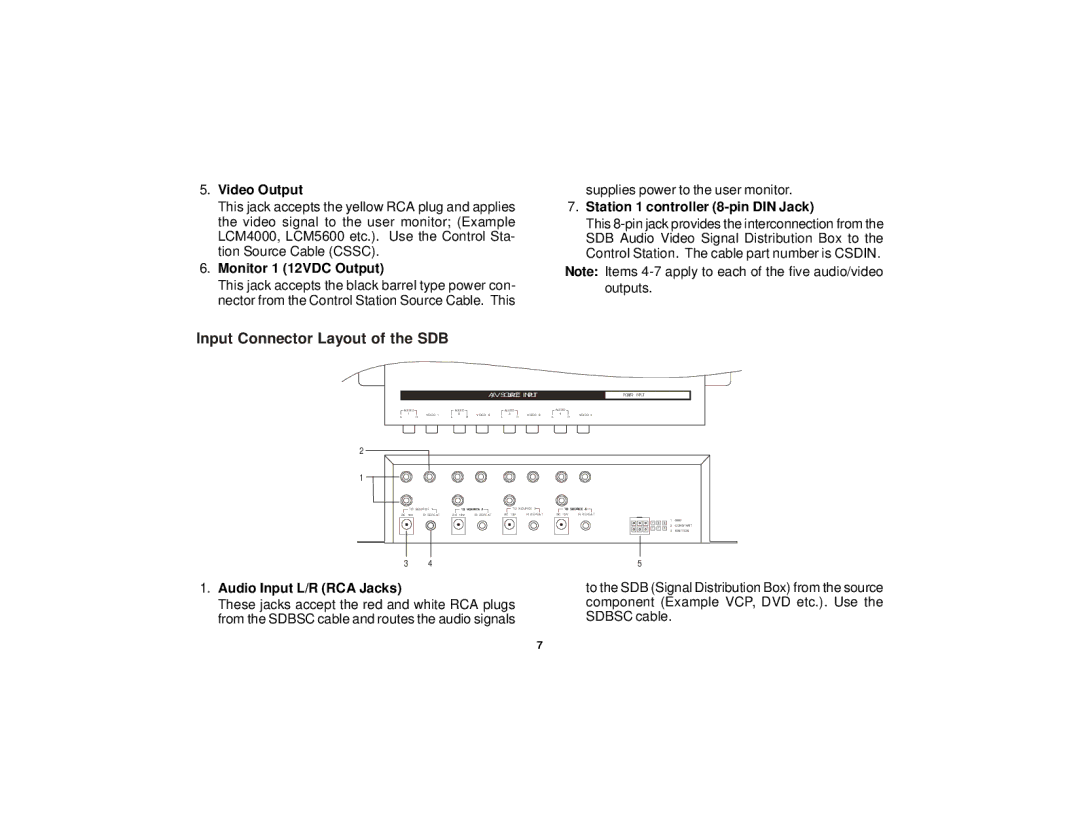
Input Connector Layout of the SDB
A/V SOURCE INPUT
POWER INPUT
AUDIO |
| AUDIO |
| AUDIO |
| AUDIO |
|
1 | VIDEO 1 | 2 | VIDEO 2 | 3 | VIDEO 3 | 4 | VIDEO 4 |
L | R | L | R | L | R | L | R |
2
1
|
| TO SOURCE 1 |
|
|
|
|
|
|
| TO SOURCE 3 |
|
| ||
DC 12V | IR REPEAT | DC 12V | IR REPEAT | DC 12V | IR REPEAT | DC 12V | IR REPEAT | |||||||
|
| 1 – GND |
1 | 2 | 2 |
|
| 2 – CONSTANT |
1 | 1 | 3 |
|
| 3 – IGNITION |
3 4
1.Audio Input L/R (RCA Jacks)
These jacks accept the red and white RCA plugs from the SDBSC cable and routes the audio signals
5
to the SDB (Signal Distribution Box) from the source component (Example VCP, DVD etc.). Use the SDBSC cable.
7