| 12 |
| INS TALLA | TIO N | PR OC | ED U | RE |
| ||||
|
|
| ||||||||||
|
|
|
|
|
|
|
|
|
|
|
|
|
|
|
|
| D o not a llowpeop | leto wa lkunder or | |||||||
|
|
|
| a round the door | duringthe installation | |||||||
|
|
|
| proc | ess a s serious injuryca | n oc | c ur. | |||||
|
|
|
|
|
|
|
| |||||
|
| NOTE: | The opener | can | be insta lled | on | either side | |||||
|
| of the door. | The followinginstructions | are for | ||||||||
|
| RIG | HT | H AN | D | IN STALLATIONS | (a s ilustrated i.e. | |||||
|
| inside thega rage look ing out). For | leftha nd | |||||||||
|
| installations, | reversetheinstructionterminology | |||||||||
|
| (eg LEFT | for RI GHT | etc) . |
|
|
| |||||
P reparat ion:
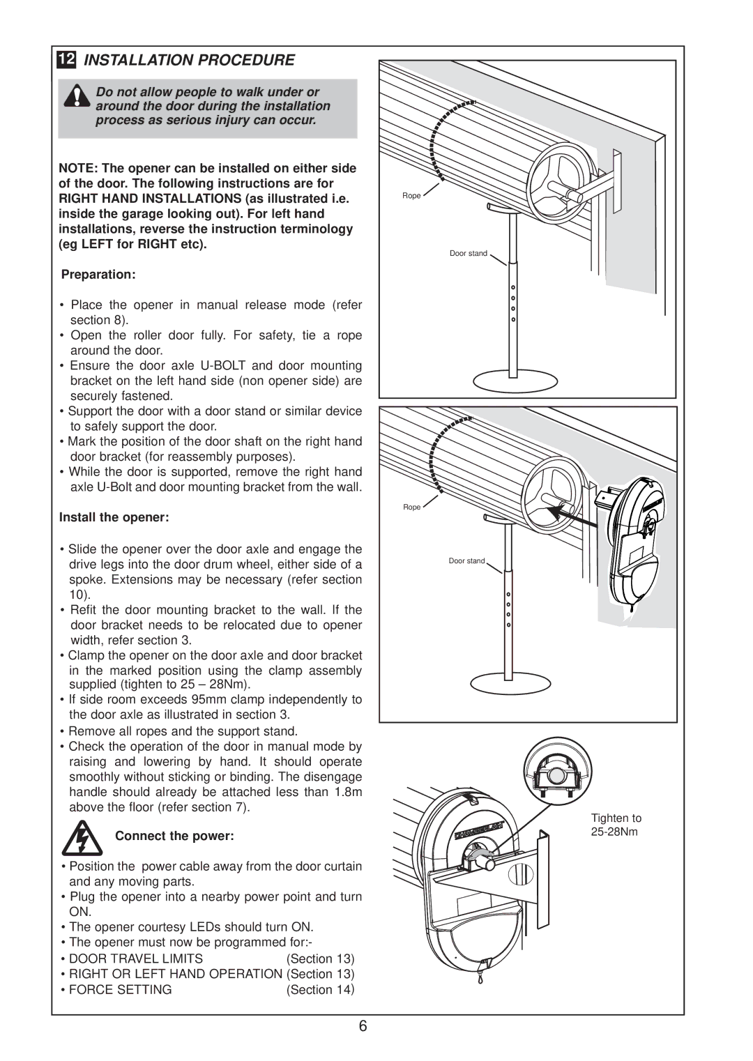
•P lace the openerin manual releasemode (refer section8) .
•Op en the roller door fully.For safety,tiea rope
aroundthe door. |
|
•E nsurethe door axle | and doormounting |
bracketon the leftha nd side (non openerside) are | |
securelyfastened. |
|
•S upporthe doorw itha doorstand orsimilardevice | |
tosafelysupportthe door. |
|
•Ma rkthe positionofthedoorsha ftontherighthand | |
doorbracket(forreassemblypurposes). | |
•While the dooris supported, remove the righthand | |
axleU- Boltand doormounting bracketfromthe wall. | |
Installtheopene r: |
|
•Slidetheopeneroverthedooraxleand enga ge the | |
drivelegs intothedoordrum whe el,eithersideofa | |
spoke. Extensions may be necessary(refersection | |
1 0 ). |
|
•Refitthe doormountingbrackettothe wall.Ifthe | |
doorbracketneeds tobe relocated due to opener | |
width, refersection3. |
|
•Clampthe openeronthe dooraxleand doorbracket | |
inthe marked positionusing | the clampassembly |
supplied(tighten to25 | |
•Ifsideroom exceeds 95mm clampindependentlyto | |
the dooraxleas ilustrated in section 3. | |
•Re move allropes and thesupportstand.
•Ch eck the operation ofthe doorinmanualmode by raisingand lowering by ha nd. Itshould operate smoothlyw itho utstickingorbinding . The disengage
h andlesh ouldalready be attached lessthan1.8m above the floor(refersection 7) .
C onnec tthepowe r:
•P ositionthe powercableawa y fromthedoorcurtain and any moving parts.
•P lug the openerintoa nearby power pointand turn
ON. |
|
|
|
|
|
|
•Th | e openercourtesy LEDs should turnON. | |||||
•Th | e openermustnow be programmed for:- | |||||
•DOOR |
| TR | AV EL | LIM ITS | (Section13) | |
•RIGH | T | O R | LEFT | H AN D OPERATION | (Section13) | |
•FOR |
| CE | SETTI NG |
| (Section14 ) | |
Rope ![]()
Door stand
Rope ![]()
Door stand
Tighten to
6
