Installation Instructions | FHP |
INSPECT THE UNIT BEFORE INSTALLING
WARNING: Watch for pinch points. Do not put your fingers between movable parts.
1.Carefully inspect the FHP for shipping damage. If any damage is apparent, call your carrier claims agent and do not continue with the installation until the carrier has reviewed the damage.
NOTE: Read all instructions before starting installation.
2.Lay out components to ensure you have all the required parts before proceeding (see FHP drawing on page 2).
FHP INSTALLATION
WARNING: It is the responsibility of the installer to verify that the surface to which the FHP is anchored will safety support the combined load of all attached components and equipment.
Install the FHP as follows:
1.Determine the exact mounting location prior to installation, considering the unit’s swing radius.
WARNING: Improper installation can result in serious per- sonal injury! Make sure that the structural mem- bers can support a redundant weight factor five times the total weight of the equipment: if not, reinforce the structure before installing the FWP.
2.Secure the ceiling plate at the desired location.
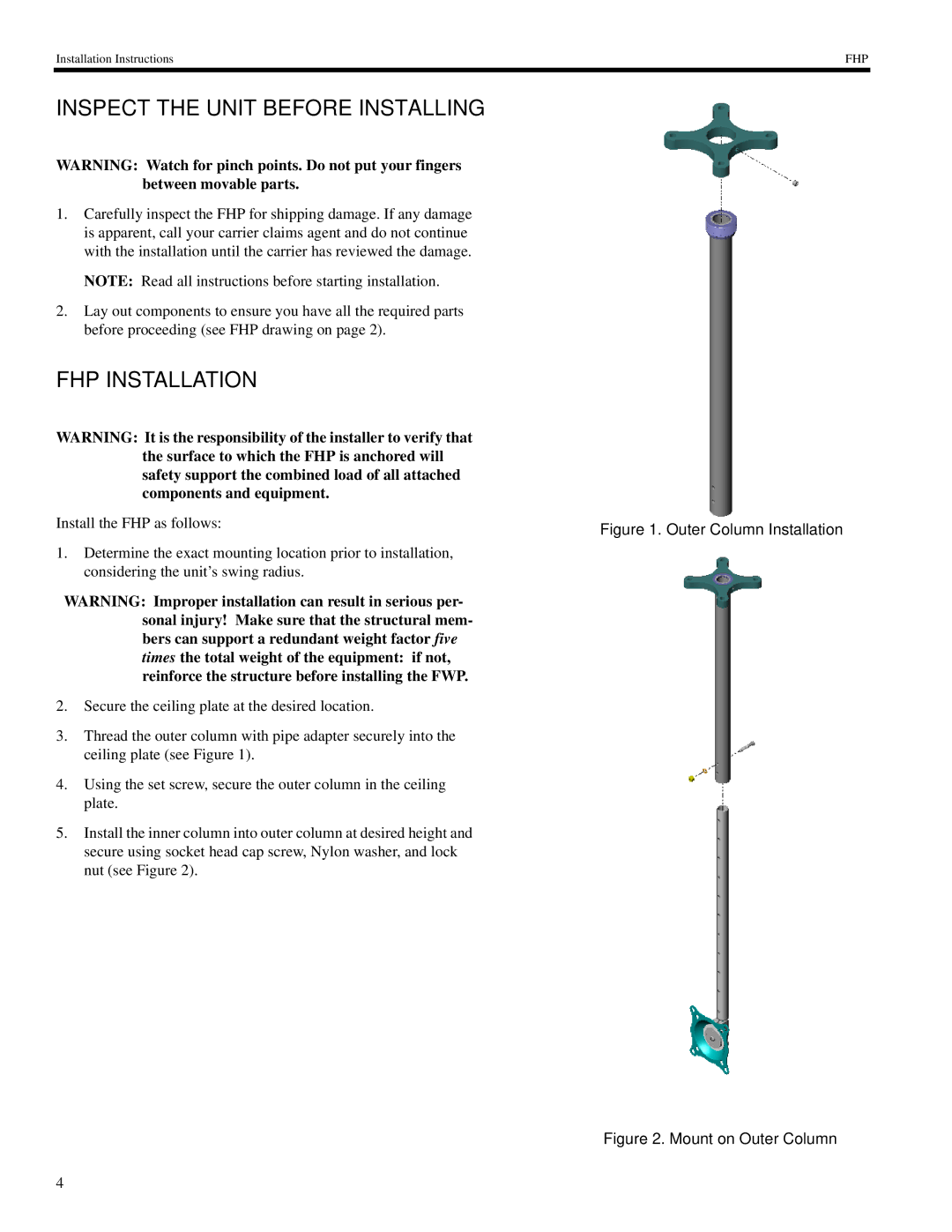
3.Thread the outer column with pipe adapter securely into the ceiling plate (see Figure 1).
4.Using the set screw, secure the outer column in the ceiling plate.
5.Install the inner column into outer column at desired height and secure using socket head cap screw, Nylon washer, and lock nut (see Figure 2).
Figure 1. Outer Column Installation
Figure 2. Mount on Outer Column
4