PNR Series | Installation Instructions |
Cable Management
WARNING: IMPROPER INSTALLATION CAN LEAD TO SERIOUS PERSONAL INJURY OR DAMAGE TO EQUIPMENT! Make sure cables do not run through pinch points.
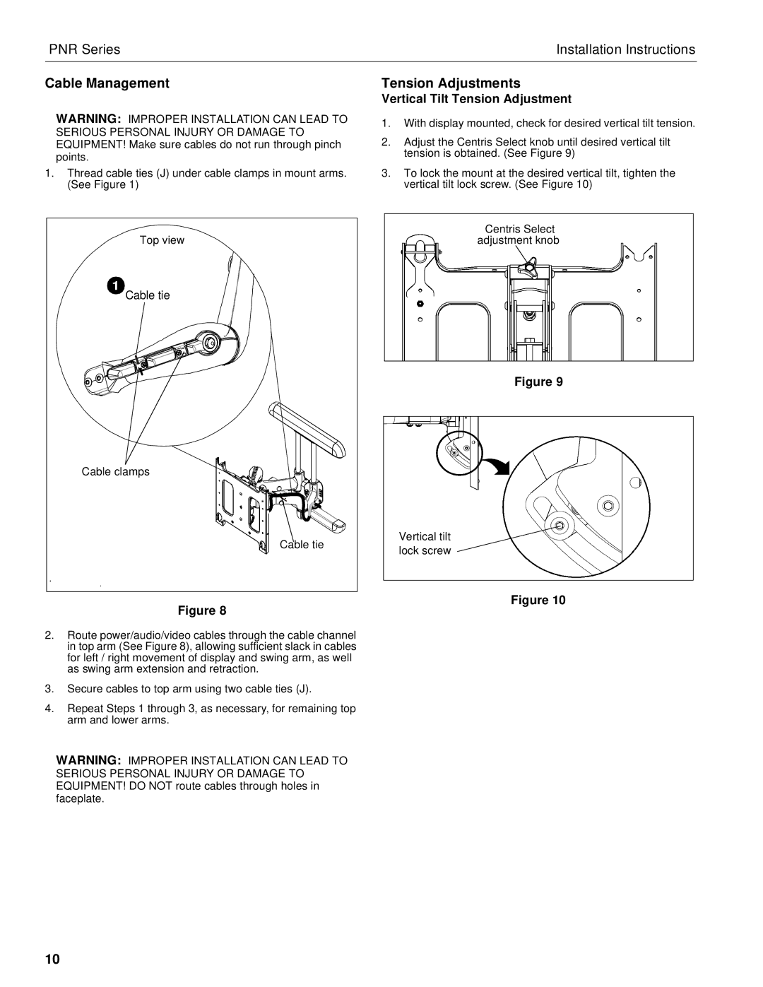
1.Thread cable ties (J) under cable clamps in mount arms. (See Figure 1)
Tension Adjustments
Vertical Tilt Tension Adjustment
1.With display mounted, check for desired vertical tilt tension.
2.Adjust the Centris Select knob until desired vertical tilt tension is obtained. (See Figure 9)
3.To lock the mount at the desired vertical tilt, tighten the vertical tilt lock screw. (See Figure 10)
Top view |
1 |
Cable tie |
Cable clamps |
Cable tie |
Figure 8
2.Route power/audio/video cables through the cable channel in top arm (See Figure 8), allowing sufficient slack in cables for left / right movement of display and swing arm, as well as swing arm extension and retraction.
3.Secure cables to top arm using two cable ties (J).
4.Repeat Steps 1 through 3, as necessary, for remaining top arm and lower arms.
WARNING: IMPROPER INSTALLATION CAN LEAD TO SERIOUS PERSONAL INJURY OR DAMAGE TO EQUIPMENT! DO NOT route cables through holes in faceplate.
Centris Select |
adjustment knob |
Figure 9
Vertical tilt |
lock screw |
Figure 10
10