Stacking Frame Installation Instructions
Projector Alignment
Ensure the stacking legs are extended at least 1” and are slightly loose before aligning the projectors.
Stacked projectors must be correctly aligned to one another so the resulting display is optimized and as sharp as possible. If hoisting the stack do so first and then align. To maintain alignment lock all stacking hardware into place.
• | Always align the fixed projector. For floor or | ||||||||
| align the bottom projector. In hoisted stacks, align the top projector. | ||||||||
• |
|
|
|
| RELEASED | ||||
Leg nuts must be loosened before alignment; otherwise the stacking mounts will | |||||||||
| not turn and allow movement of the projector. |
|
|
| |||||
1. | Position the fixed projector’s image as desired and align the other image(s) to it. | ||||||||
2. | To distinguish between the images, enable Red for one display and Green for the | ||||||||
| other. For more information, refer to the manual supplied with the projector. | ||||||||
3. |
|
|
|
|
| Control | 2006 | ||
Minimize each projector’s zoom until the images are focused. | |||||||||
4. | Adjust the zoom and lens offset on the top p jector to precisely move its test | ||||||||
| pattern display onto the bottom test pattern. When it is properly aligned all the | ||||||||
|
| OFFICIALLY |
|
|
|
|
| ||
| Red/Green grid lines in the combined image will turn Yellow. | ||||||||
| • |
|
| Document |
|
|
|
| |
| If all lines are | ||||||||
| • |
| September | 8, |
|
| |||
| If alignment needs improvement, |
|
|
| |||||
|
| proceed to Step 5. |
|
|
|
|
|
| |
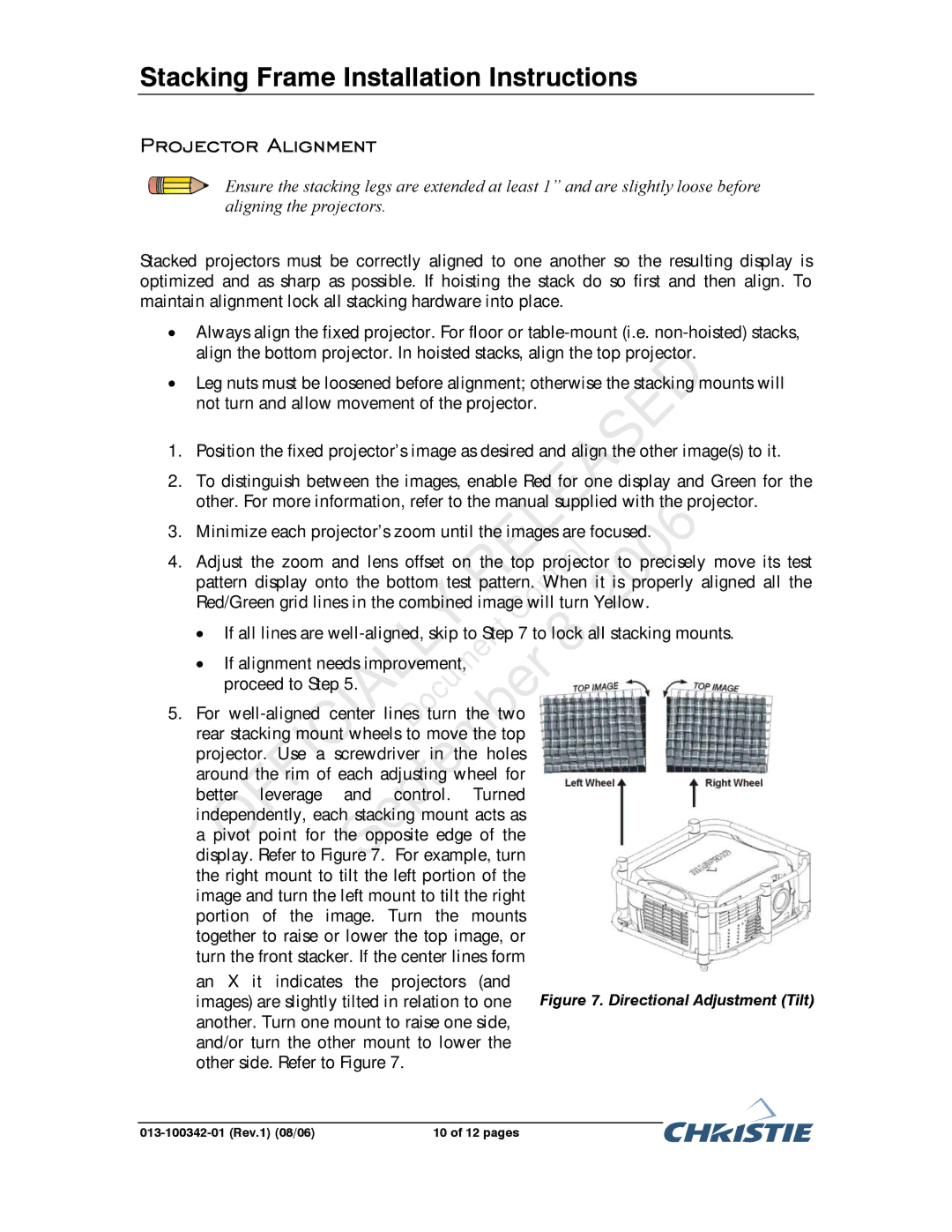
5. | For |
|
|
| |||||
| rear stacking mount wheels to move the top |
|
|
| |||||
| projector. Use a screwdriver in the holes |
|
|
| |||||
| around the rim of each adjus ing wheel for |
|
|
| |||||
| better leverage | and control. Turned |
|
|
| ||||
| independently, each stacking mount acts as |
|
|
| |||||
| a pivot point for the opposite edge of the |
|
|
| |||||
| display. Refer to Figure 7. For example, turn |
|
|
| |||||
| the right mount to tilt the left portion of the |
|
|
| |||||
| image and turn the left mount to tilt the right |
|
|
| |||||
| portion of the image. Turn the mounts |
|
|
| |||||
| together to raise or lower the top image, or |
|
|
| |||||
| turn the front stacker. If the center lines form |
|
|
| |||||
| an X it indicates the projectors (and | Figure 7. Directional Adjustment (Tilt) | |||||||
| images) are slightly tilted in relation to one | ||||||||
| another. Turn one mount to raise one side, |
|
|
| |||||
| and/or turn the other mount to lower the |
|
|
| |||||
| other side. Refer to Figure 7. |
|
|
|
|
| |||
|
|
|
|
|
| ||||
| 10 of 12 pages |
|
|
| |||||