Connecting the Interface Cables and Checking the LEDs
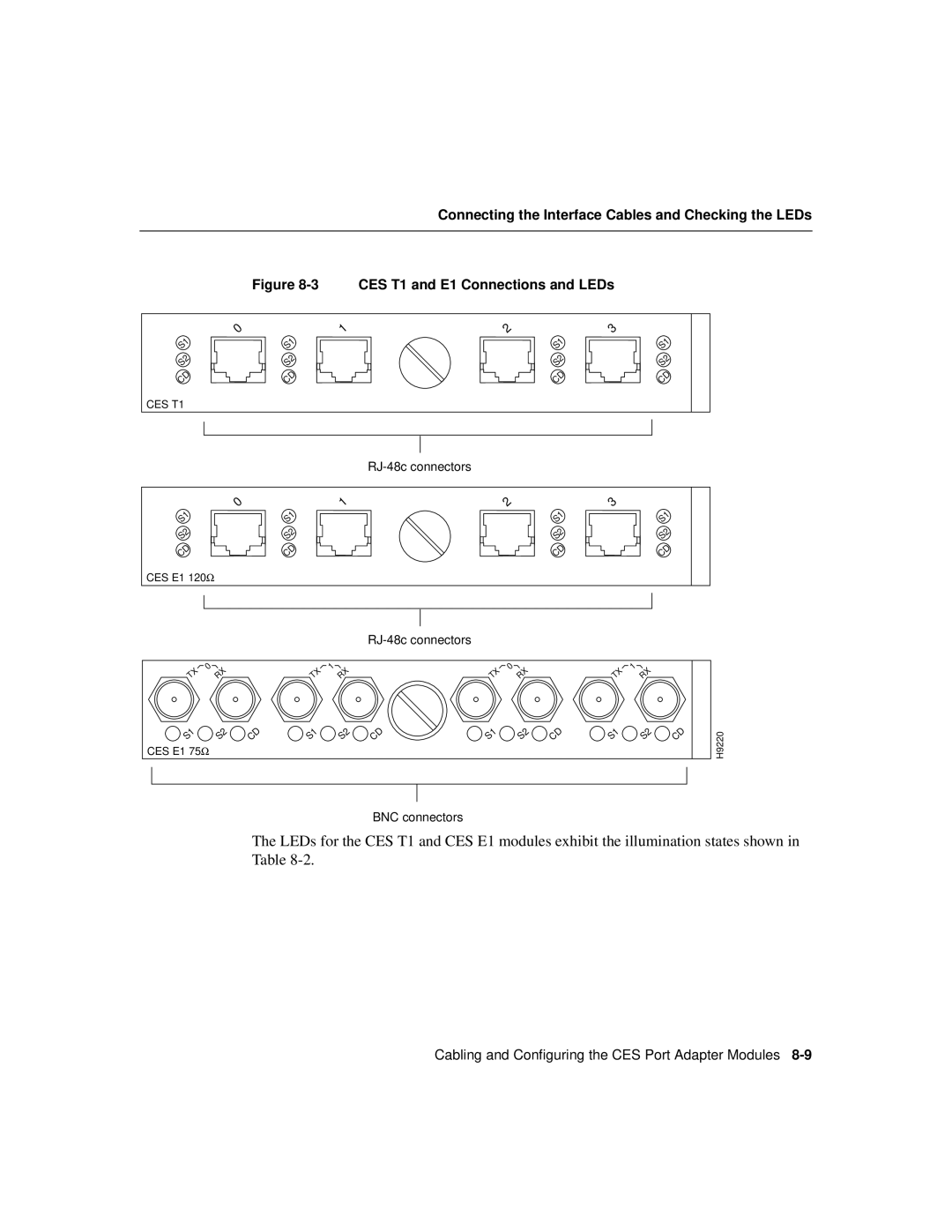
| Figure | CES T1 and E1 Connections and LEDs | |
0 | 1 | 2 | 3 |
S1 | S1 | S1 | S1 |
S2 | S2 | S2 | S2 |
CD | CD | CD | CD |
CES T1 |
|
|
|
|
|
|
|
0 | 1 | 2 | 3 |
S1 | S1 | S1 | S1 |
S2 | S2 | S2 | S2 |
CD | CD | CD | CD |
CES E1 120Ω |
|
|
|
TX | 0 | RX |
| TX | 1 | RX |
| TX | 0 | RX |
| TX | 1 | RX |
|
|
|
|
|
|
|
|
|
|
| ||||||||
S1 |
| S2 | CD | S1 |
| S2 | CD | S1 |
| S2 | CD | S1 |
| S2 | CD | H9220 |
CES E1 75W |
|
|
|
|
|
|
|
|
|
|
|
|
|
| ||
BNC connectors
The LEDs for the CES T1 and CES E1 modules exhibit the illumination states shown in Table
Cabling and Configuring the CES Port Adapter Modules