Front Panel Description
LEDs
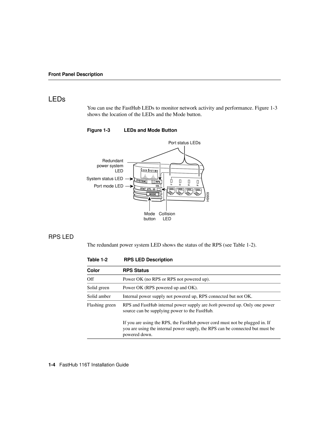
You can use the FastHub LEDs to monitor network activity and performance. Figure
Figure 1-3 LEDs and Mode Button
Port status LEDs
Redundant power system
LED ![]()
![]()
![]()
![]()
![]()
![]()
![]()
![]()
![]()
![]()
![]()
![]() System status LED
System status LED ![]()
![]()
Port mode LED ![]()
![]()
Mode Collision button LED
H9909
RPS LED
The redundant power system LED shows the status of the RPS (see Table
Table | RPS LED Description |
|
|
Color | RPS Status |
|
|
Off | Power OK (no RPS or RPS not powered up). |
|
|
Solid green | Power OK (RPS powered up and OK). |
|
|
Solid amber | Internal power supply not powered up, RPS connected but not OK. |
|
|
Flashing green | RPS and FastHub internal power supply are both powered up. Only one power |
| source can be supplying power to the FastHub. |
| If you are using the RPS, the FastHub power cord must not be plugged in. If |
| you are using the internal power supply, the RPS can be connected but must be |
| powered down. |
|
|