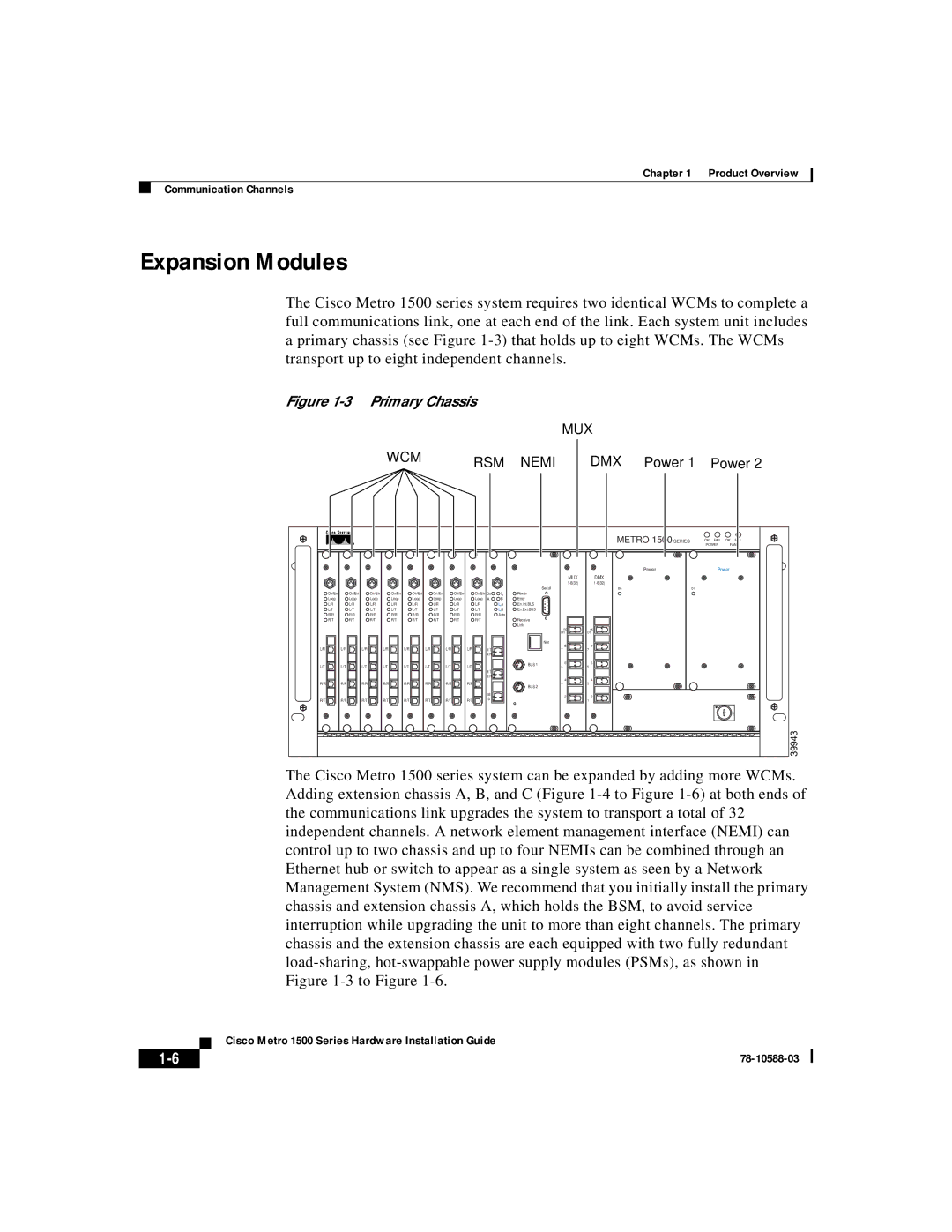
1500 specifications
Cisco Systems, a leader in networking and IT solutions, has a long history of providing innovative technologies for businesses of all sizes. One of their notable offerings is the Cisco Systems 1500 series, a robust and flexible networking solution designed to meet the demands of modern enterprises. The Cisco 1500 series is particularly recognized for its capabilities in delivering high-performance routing and switching services, ensuring reliable connectivity across various environments.One of the main features of the Cisco 1500 series is its ability to operate in diverse environments, including branch offices and remote locations. Backed by Cisco's proprietary software, the 1500 series includes advanced routing protocols that enhance performance while optimizing bandwidth usage. This is crucial for businesses that rely on real-time data transmission for applications like voice over IP (VoIP) and video conferencing.
In addition to routing capabilities, the Cisco 1500 series is designed with enhanced security features. Integrated firewalls, intrusion prevention systems (IPS), and secure VPN options ensure that data remains protected from potential threats. The ability to implement rich security policies at branch locations is essential for organizations looking to safeguard sensitive information while maintaining regulatory compliance.
Another key characteristic of the Cisco 1500 series is its support for Cisco's Software-Defined Wide Area Network (SD-WAN) technology. This feature allows businesses to manage their WAN connections more efficiently, increasing agility and reducing costs. By utilizing software-based controls, organizations can optimize traffic flows and respond to changing network conditions in real-time.
Scalability is an essential aspect of the Cisco 1500 series, providing businesses the flexibility to grow without major overhauls of their infrastructure. The ability to support multiple connections and integrate seamlessly with cloud services makes the 1500 series an ideal choice for hybrid environments.
Additionally, the Cisco 1500 series is equipped with management and monitoring tools that enhance visibility into network performance. This includes Cisco DNA Center and other network management platforms that deliver insights, automate processes, and streamline operations.
In summary, the Cisco Systems 1500 series combines high-performance routing, robust security, support for SD-WAN, and scalability to meet the challenges of contemporary networking. As companies increasingly adopt digital transformation strategies, solutions like the Cisco 1500 series are vital for ensuring seamless connectivity, security, and adaptability in an ever-evolving technological landscape.

